Line Calibration for Push Broom NIR Imaging Sensors
Line calibration for push-broom NIR sensors locks spatial-spectral pixel registration against mechanical drift, preventing costly sorting errors.


Slit
An entrance aperture cut to thirty microns sits unbolted on an optical rail in a Shenzhen assembly bay. The focal plane array behind it, an indium gallium arsenide detector chilled by an integrated thermoelectric cooler to minus twenty degrees Celsius, registers light across nine hundred to seventeen hundred nanometers. Push-broom hyperspectral imaging collects an entire spatial line simultaneously while dispersing wavelengths across the orthogonal sensor axis.
Spatial coordinates occupy horizontal sensor columns. Spectral channels occupy vertical rows. Misalignment between the physical entrance slit and the underlying pixel array ruins both dimensions instantly.
Technicians often align the optical barrel by eye before tightening set screws with an uncalibrated hex driver. When the slit tilts by two milliradians relative to the detector array columns, spectral bands bleed into adjacent spatial pixels at the line edges. Off-axis illumination exacerbates this mechanical skew.
Optical dispersion through a transmissive prism-grating-prism element demands that the physical slit image falls precisely along a single detector row across all intended wavelengths.
A tilt exceeding one quarter of a pixel width across a five-hundred-pixel line shifts spectral band assignments by up to four nanometers at the array margins.
Collimating optics project the scene through the slit before the disperser splits the incoming beam. Optical aberrations distort this geometric mapping. Smile distortion curves the slit image along the dispersion axis, bending a straight monochromatic line into an arc.
Keystone distortion magnifies or compresses the spatial extent as a function of wavelength, converting a rectangular spatial footprint into a trapezoid. Mechanical assembly tolerances directly dictate the initial severity of both geometric defects.

Mechanical Tolerancing across Array Dimensions
Machined housing components carry machining tolerances of plus or minus ten microns when sourced from domestic CNC mills in Dongguan. Thermal cycling between twenty and forty-five degrees Celsius alters the relative mechanical distance between the slit mount and the collimator lens cell. Aluminium 6061 housings exhibit a thermal expansion coefficient of twenty-three parts per million per Kelvin.
Brass or invar sleeves reduce thermal expansion mismatches against optical glass elements. Precision assembly rigs track slit positioning through high-magnification alignment cameras operating under monochromatic green illumination.
Slit orientation adjustments rely on differential micrometer drives mounted directly to the calibration fixture. The operational alignment sequence follows strict mechanical and optical steps:
- Aperture centering places the mechanical slit center within three microns of the optical axis before tightening base clamps. Secondary shifts during clamp torque application ruin downstream alignments immediately.
- Rotational nulling spins the barrel mount until a fifty-four-nanometer line source illuminates identical row indices across the detector center and edges. Technicians monitor live pixel readouts on an oscilloscope trace.
- Axial focus tracking shifts the collimator doublet along the z-axis to minimize the full width at half maximum of the slit image. Defocused slits broaden spectral response functions past sensor specifications.
- Torque locking fixes radial locking screws to zero point two Newton-meters in a star pattern. Skipping cross-pattern torque sequences introduces asymmetric mechanical tilt across the barrel.
Slit degradation also stems from dust accumulation and edge burrs produced during laser cutting. Chemical etching produces cleaner aperture edges than direct mechanical blade slitting. Rough edges produce spatial intensity dropouts that software calibration routines struggle to balance without raising electronic gain and amplifying sensor noise floor.
Workshop managers regularly claim that factory set screws retain factory line positions across export shipping without thread-locking compounds.

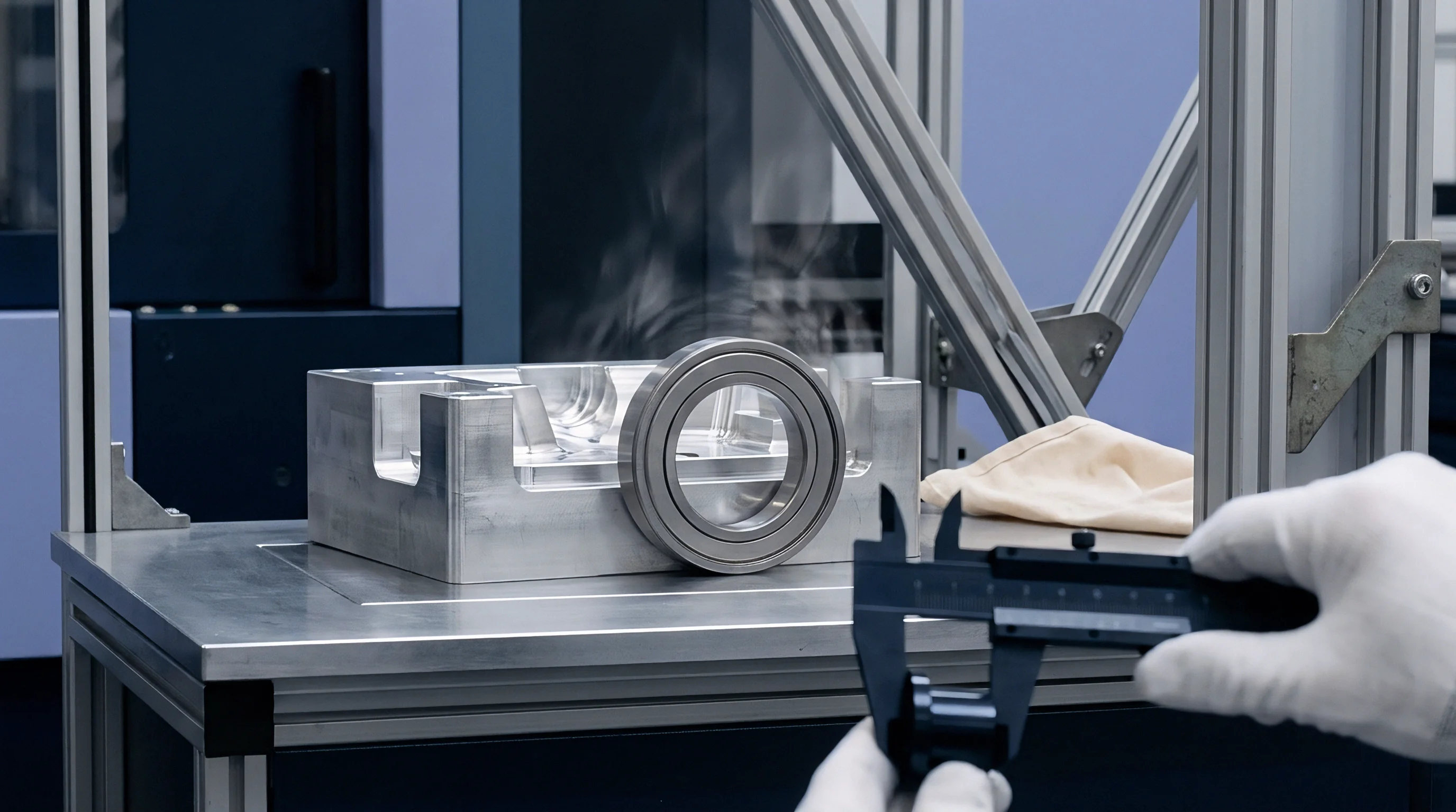
Source
Light fixtures inside an optical testing darkroom dictate calibration precision. A tungsten halogen lamp powered by a direct-current source running in constant-current mode provides smooth continuum emission across nine hundred to twenty-five hundred nanometers. Current fluctuations must stay below zero point零五 percent to prevent baseline radiometric drift during exposure cycles.
Integrating spheres coated with sintered polytetrafluoroethylene diffuse the continuum output to deliver spatial uniformity exceeding ninety-eight percent across the field of view.
Emission lamps supply narrow atomic spectral lines that fix wavelength reference points. Low-pressure mercury-argon, neon, and krypton discharge lamps provide absolute physical references that do not shift with laboratory temperature. The 912.3 nm, 1013.98 nm, 1128.7 nm, 1367.3 nm, and 1529.6 nm atomic lines provide sharp validation anchors across the near-infrared band.
Calibration labs operating under standard industrial tenders lose contractual warranty validation whenever reference light source drift records remain unlogged.
Solid-state absorption standards complement gas emission lamps. Rare-earth oxide glasses containing holmium, erbium, and dysprosium present sharp spectral absorption troughs at documented wavelengths. Reflectance standards made of pressed PTFE provide diffuse white targets for relative reflectance conversions.
The calibration rig pairs these elements to isolate spatial non-uniformities from spectral response variations.

Radiometric Flat Field Acquisition
Detector arrays exhibit pixel-to-pixel variations in dark current and quantum efficiency. Dark signal non-uniformity stems from silicon or InGaAs substrate defects and localized thermal gradients across the sensor die. Photo-response non-uniformity arises from variations in pixel surface area, antireflection coating thickness, and read-out integrated circuit gain stages.
Correcting these differences requires collecting dark frames and illuminated flat-field frames across multiple integration times.
A standard two-point correction normalizes every sensor pixel through additive and multiplicative terms. The dark frame registers pure electronic and thermal background when the optical shutter remains closed. The flat-field frame captures the integration sphere aperture under stable halogen illumination at approximately seventy percent of the pixel full-well capacity.
Mathematical processing scales pixel outputs to match a uniform digital response across all active channels.
Linearity testing identifies the saturation boundary of individual pixel wells. Exposure sweeps from zero point one milliseconds to fifty milliseconds reveal non-linear response regimes where read-out amplifiers compress charges near well capacity. Applying linear calibration models to saturated pixels distorts quantitative chemical absorption measurements during operational sorting runs.
| Source Type | Calibration Role | Wavelength Range | Stability Window |
|---|---|---|---|
| Tungsten Halogen | Flat-field Radiometry | 850 to 2500 nm | 0.1 percent per hour |
| Low-Pressure Hg-Ar | Wavelength Registration | 253 to 1700 nm | 0.01 nm spectral peak |
| Rare-Earth Glass | Band Verification | 900 to 2000 nm | 0.05 nm thermal drift |
| Sintered PTFE Sphere | Spatial Uniformity Target | 250 to 2500 nm | 99.1 percent field balance |
Stray light within the spectrograph chamber degrades line calibrations. Reflections from interior barrel walls, lens bevels, and second-order diffraction orders cast unwanted photons across adjacent detector pixels. Anodized optical coatings and internal baffles attenuate secondary reflections.
Characterizing stray light involves illuminating the sensor with narrow-band laser line sources and measuring signal spillover into distant unilluminated channels.
Failure to eliminate internal stray light during primary source calibration leads directly to false chemical grading readings and scrap rejections during automated conveyor sorting.

Curvature
Optical distortions manifest as spatial smile and spectral keystone across push-broom detector arrays. Smile describes the curvature of an intrinsically straight monochromatic entrance slit onto the two-dimensional detector array. The center wavelength shifts as a function of the spatial pixel index along the slit axis.
Keystone describes the chromatic variation of magnification, causing a single spatial point on the target to illuminate different spatial pixel indices across successive wavelength channels.
Distortion values below zero point one pixels across both dimensions represent the threshold for quantitative spectroscopy without intensive algorithmic compensation. Off-the-shelf industrial spectrographs rarely meet this physical threshold without specialized corrective optics. Uncorrected distortions mix spatial boundaries with spectral absorption bands, producing false classification edges along sample borders on fast conveyor belts.
Physical causes of smile and keystone include prism dispersion non-linearities, diffraction grating tilt errors, and spherical aberration inside collimator and focusing lens groups. Symmetrical optical designs like Offner and Dyson concentric configurations balance these aberrations better than standard Czerny-Turner or transmissive lens geometries. Offner designs utilize convex diffraction gratings to cancel primary optical aberrations across broad spectral bands.

Where Do Uncorrected Smile Errors Corrupt Sorting Decisions?
Polymer recycling sorting lines differentiate polyethylene terephthalate from high-density polyethylene using narrow hydrocarbon absorption doublets near 1210 nm and 1730 nm. A two-pixel smile error shifts the nominal band center by three nanometers between the conveyor center and the conveyor belt edge. A flake passing along the belt margin yields a distorted spectral signature that triggers an incorrect pneumatic ejector sequence.
Misclassified items contaminate recycled bales, degrading product purity grades.
Agricultural seed sorting presents identical vulnerabilities. Grain protein content correlates with subtle absorption depths around 1450 nm. Keystone errors cause the spatial bounding box of an individual grain kernel to wander across pixel columns as the detector steps through spectral bands.
Edge pixels sample background conveyor belt reflectance instead of seed reflectance at specific wavelengths, skewing chemometric classification models.
Calibration procedures map geometric distortions by recording emission line profiles across every spatial column. Polynomial fitting models calculate coordinate displacement vectors for each physical pixel. The distortion mapping process isolates specific mechanical and optical defects across the line:
- Smile displacement vectors reveal parabolic wavelength shifts caused by grating field curvature. Residual errors increase quadratically from the optical center toward array corners.
- Keystone distortion matrices trace trapezoidal spatial scaling across spectral bands. Chromatic aberrations in refractive focusing optics cause spatial magnification variations across bands.
- Rotational tilt offsets measure mechanical angle errors between the physical slit and the focal plane array. Slit rotation mixes spatial and spectral coordinates linearly across the whole detector.
- Sub-pixel interpolation residuals mark computational artifacts generated when resampled grids smooth narrow spectral absorption peaks. Sharp absorption peaks lose peak depth during cubic spline transformations.
Bilinear, bicubic, or thin-plate spline interpolation algorithms resample raw camera frames onto an idealized rectilinear coordinate grid. Resampling requires digital signal processing horsepower that increases camera latency. High-speed conveyor applications operating at five hundred lines per second demand hardware-level field-programmable gate array implementations to complete interpolation within the available line period.
Optical alignment tolerances achieved during cleanroom assembly govern sensor longevity far more effectively than digital resampling matrices patched into software drivers.
Digital correction cannot recover spatial or spectral resolution lost to severe optical aberration. Blurring across multiple pixels permanently lowers the modular transfer function of the optical system. Software rectification redistributes sensor energy across adjacent digital bins, adding computational noise to low-signal spectral bands.
A calibrated lens cell assembled without mechanical strain holds its distortion mapping across temperature swings.


Motion
Push-broom sensors build a two-dimensional spatial image by moving over a target or allowing an industrial conveyor to carry objects past a stationary field of view. Synchronization between line acquisition rates and physical conveyance speed defines image geometry. Uneven line spacing compresses or stretches spatial features along the motion axis.
Forward motion speed must match the cross-track instantaneous field of view precisely to achieve square spatial pixels.
Line exposure time limits maximum scan speeds. An integration time of two milliseconds permits a maximum theoretical line rate of five hundred frames per second. Operating a conveyor at one meter per second under these conditions requires an along-track ground sampling distance of exactly two millimeters.
Conveyor speed variations introduce spatial distortion that cannot be corrected by static optical line calibrations.

Can Factory Line Calibration Survive Overseas Transit?
Container transport exposes sensitive spectrograph assemblies to sustained mechanical vibration and thermal extremes. Cargo vessels cross maritime routes where ambient container temperatures fluctuate between minus ten and plus fifty-five degrees Celsius over three weeks. Standard ocean freight manifests log high-frequency vibration profiles along with severe shock impacts up to fifteen gravities during container crane handling in transshipment hubs like Ningbo and Singapore.
Optical mounts shift under sustained vibration when mechanical locknuts loosen or structural adhesive bonds creep. An optical barrel calibrated to zero point zero five pixel keystone tolerance in a cleanroom can arrive at an overseas integration dock with zero point four pixels of mechanical misalignment. Evaluating structural shift involves repeating wavelength line verification upon delivery before deploying systems to operational plant floors.
| Stress Parameter | Operating Limit | Transit Survival Limit | Failure Indicator |
|---|---|---|---|
| Random Vibration | 0.5 g RMS (10-500 Hz) | 3.2 g RMS (5-500 Hz) | Slit rotational tilt shift |
| Mechanical Shock | 5 g peak, 11 ms pulse | 25 g peak, 6 ms pulse | Collimator lens decenter |
| Thermal Gradient | 0.5 deg C per minute | 3.0 deg C per minute | Adhesive bond delamination |
| Operating Temp | 15 to 35 deg C | -20 to 65 deg C | TEC cooler seal failure |
Rotary encoders mounted directly to conveyor drive shafts generate hardware trigger pulses that command camera acquisitions. Pulse drops or encoder wheel slippage corrupt line acquisition timing. When line pulses fall out of sync with conveyor travel, images suffer from spatial shearing and geometric distortion along the scan direction.
Integration time adjustments alter the thermal balance of the detector package. Extending exposure times to gather signal from low-reflectance materials increases background dark current. Cooler controllers must adjust current consumption to maintain stable substrate temperatures.
Fluctuating sensor temperatures introduce spectral calibration drift during continuous multi-hour manufacturing shifts.
Export procurement contracts that omit MIL-STD-810H vibration and transit shock clauses transfer all financial risk of optical calibration failure onto the receiving importer.
International sales agreements define warranty liabilities based on physical transit packaging standards. Incorporating standardized shock data loggers inside shipping crates establishes clear accountability when mechanical impacts knock internal optical elements out of alignment during overseas transit.

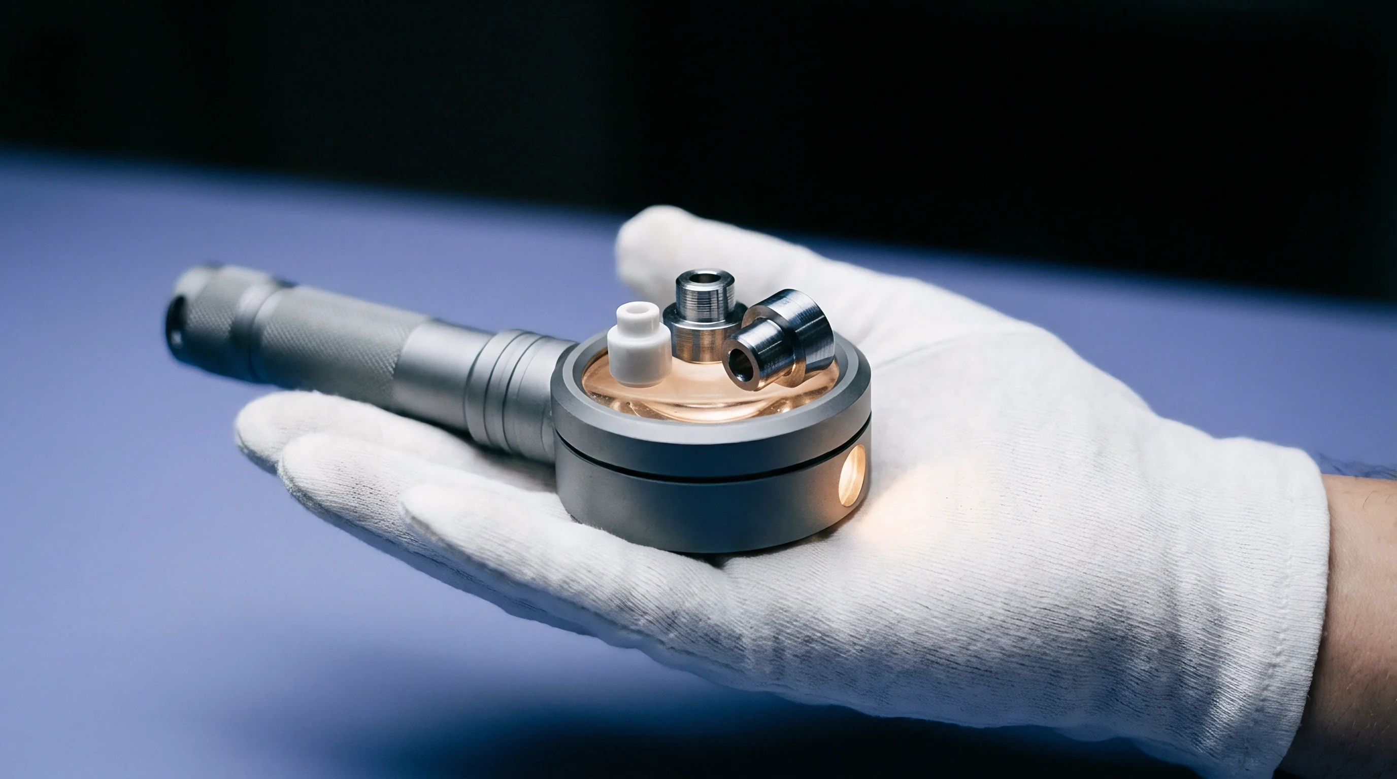
Tolerancing
Procurement dossiers for near-infrared push-broom sensors specify spatial resolution, spectral band count, signal-to-noise ratios, and maximum allowable distortion figures. Discrepancies between vendor marketing brochures and delivered factory acceptance test certificates cause severe friction during project handoffs. Chinese optics suppliers frequently quote smile and keystone specifications measured only at the central five percent of the detector array.
Real-world sorting operations utilize the complete field of view across all active sensor columns.
Factory acceptance testing requires standardized inspection benches capable of evaluating the complete focal plane. A multi-line spectral lamp coupled to an integrating sphere illuminates the sensor through a specialized calibration reticle. The reticle presents a series of precision chrome-on-glass pinholes or vertical line bars spaced evenly across the spatial field.
Technicians record raw data cubes to extract spectral centroids and spatial line widths across every pixel coordinate.

Analytical Verification of Spectral Centroids
A rigorous acceptance protocol measures spectral line positions using Gaussian or Voigt profile peak fitting. Centroid calculations determine the center of mass for each emission peak with sub-pixel precision. Wavelength registration accuracy must fall within zero point two nanometers of published atomic emission tables across the entire active bandwidth.
Calculating the true cost of uncalibrated optical systems reveals significant commercial exposure. Consider a plastic recycling plant operating four parallel optical sorting lines processing ten metric tons of mixed polymer flakes per hour. High-density polyethylene flakes carry an average wholesale market value of one thousand two hundred dollars per metric ton.
A spectral calibration drift of two nanometers causes an uncorrected classifier to misidentify two percent of high-value flakes as lower-grade mixed waste, diverting them into low-value streams priced at four hundred dollars per metric ton.
Operating twenty hours per day across three hundred production days yields sixty thousand metric tons of processed polymer annually. A two percent misclassification rate degrades one thousand two hundred metric tons of product. The pricing gap of eight hundred dollars per ton generates an annual commercial loss of nine hundred and sixty thousand dollars across the facility.
This recurring financial drain outstrips the initial procurement cost of precision calibration benches and ruggedized spectrograph housings within the first three months of operation.
Incoming inspection routines at the buyer site must verify vendor compliance before releasing final milestone payments. Verification audits test three fundamental operational parameters:
- Band center drift across ambient temperature sweeps between ten and forty degrees Celsius.
- Spatial non-uniformity ratios across integration sphere apertures before and after two-point flat-field calibrations.
- Keystone distortion values across the five outermost spatial columns on both array edges.
Suppliers facing tight delivery schedules occasionally bypass full spatial-spectral calibration matrix acquisition, shipping cameras pre-loaded with generic factory profile coefficients. Deploying generic calibration profiles onto sensors with unique physical assembly variances degrades spectral band resolution across industrial machine vision lines.
The core dilemma facing deployment engineers remains whether real-time onboard FPGA distortion rectification can ever fully match the baseline radiometric fidelity delivered by stable, strain-free optomechanical engineering on the factory floor.