Automated Machine Vision Calibration Strategies for Variable Chemical Substrates
Automated vision calibration for variable chemical substrates requires real-time dual-wavelength exposure and motorized solvent-resistant target profiles.

Film

Chemical Surface Reflectance Mechanics
Continuous wet chemical coatings on moving webs shift optically throughout a run. Thickness fluctuates across the web width from slot-die pressure instability and uneven solvent flash-off, altering how the wet film scatters incident light. Over the moving substrate, a line-scan camera picks up shifting specular reflections as sol-gel cures into dry polymer.
Standard static calibration cannot compensate, because gloss levels change non-linearly across the exposure zone.
In fluoropolymer coating lines for PET backsheets at a Suzhou plant, substrate lots from different suppliers showed surface roughness ranging from 0.12 to 0.48 microns Ra. That spread alters scatter angles relative to the line-scan optical axis. Simply bumping fixed gain thresholds fails to recover lost contrast, leaving the sensor to register false voids wherever light scatters clear of the lens aperture.
Substrate surface roughness variations alter specular reflection geometry and invalidate single-point intensity calibration thresholds across web processing lines.
Measuring reflectance on shifting coatings requires distinct photometric channels. Diffuse lighting isolates bulk absorption from surface scatter, coaxial units catch gloss anomalies, and dark-field ring arrays expose surface micro-voids. At line speeds above 45 meters per minute, these channels must be separated without sacrificing frame rates.

Dynamic Refractive Index Variations
As toluene or methyl ethyl ketone evaporates from an applied photoresist layer during line transit, the local refractive index rises from 1.38 to 1.52 across a three-meter drying zone. Light entering the chemical film refracts at shifting angles as drying progresses. A fixed lens calibrated against dry reference stock blurs when focused on the web two meters downstream from the slot-die head.
Dual-wavelength strobing tracks this index shift in real time by alternating 405 nanometer blue LED pulses with 850 nanometer near-infrared illumination. The 405 nanometer blue light reflects off the air-coating interface to map surface topography, while the 850 nanometer near-infrared band cuts through uncured resin to reach the base substrate, isolating coat weight. Processing pipelines then calculate local film thickness directly from the phase displacement between the two wavelengths.
Setting optical thresholds that reliably distinguish localized evaporation gradients from genuine micro-void defects remains the central calibration problem at production speeds.


Optics
Multispectral Strobe Illumination Geometry
Calibration across dynamic coatings starts with illumination geometry. Conventional light fields lose up to 22 percent of their intensity near the borders of a two-meter web, and lens vignetting compounds the drop until edge pixels report false low optical densities. Flat-field correction matrices balance these losses by normalizing individual pixel sensitivities across the entire sensor array.
Thermal stability in the LED array dictates optical consistency across an eight-hour shift. When junction temperatures climb from 25 to 60 degrees Celsius, red LED output drops by 0.18 percent per degree, skewing the emission spectrum. Color line-scan cameras easily misread that shift as photoresist dye degradation or bad mix ratios.
Liquid-cooled mounting plates and constant-current drivers keep this spectral intensity drift under 0.5 percent during sustained runs.
Uncooled LED light engines drift up to eight percent in peak output intensity across a single twelve-hour manufacturing shift.
Cross-polarization cuts surface glare off wet solvent layers. Linear polarizers on the LED arrays align incoming light perpendicular to an analyzer on the camera lens, blocking specular reflection while letting subsurface scatter pass through. For internal phase-separation flaws, this cross-coupling sharpens image contrast by 300 percent.
Lens Aberration and Vignetting Compensation
Lens vignetting and edge distortion degrade boundary measurements unless optics are matched to the web geometry. High-resolution telecentric lenses keep magnification constant across wide webs even when the film flutters vertically. Standard entocentric lenses, by contrast, introduce up to 3.5 percent distortion near the margins, corrupting defect sizing on continuous rolls.
| Wavelength Range (nm) | Target Chemical Layer | Optical Dynamic Range (dB) | Calibration Standard |
|---|---|---|---|
| 365 (UV) | Optical Clear Adhesives | 54.2 | PTFE Diffuse Tile |
| 470 (Blue) | Uncured Photoresists | 62.8 | Barium Sulfate Target |
| 530 (Green) | Polyimide Coatings | 68.1 | Anodized Aluminum Scale |
| 850 (NIR) | Lithium Battery Slurry | 71.5 | Calibrated Ceramic Matrix |
Chromatic aberration shifts the focal plane when switching illumination wavelengths; uncorrected lenses wander by up to 180 microns between 400 and 900 nanometers. Achromatic doublets align focal planes across visible and near-infrared bands, keeping images sharp during rapid multispectral strobing.
Maintaining calibration accuracy on continuous coating lines requires logging illumination output against dark-current baseline values at every shift change.

Target
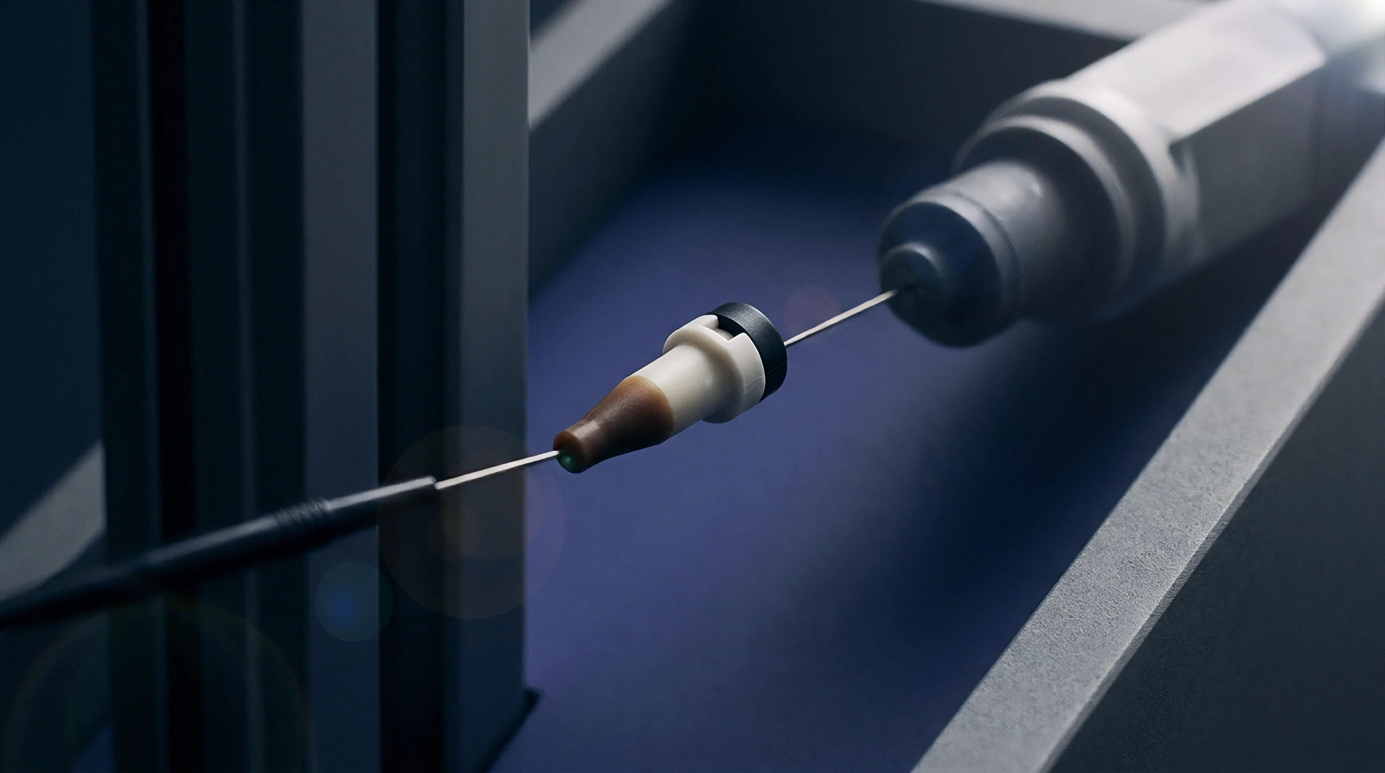
Can Ceramic Targets Withstand Solvent Vapors?
Enclosed coating zones expose calibration targets to aggressive solvent atmospheres. Vapors from acetone, N-Methyl-2-pyrrolidone, and xylene degrade paper and standard glass-photolithography targets within weeks, dissolving gelatin layers and delaminating photo-etched metal patterns.
Sintered alumina ceramic targets withstand these organic solvents, holding spatial geometry down to 0.5 micron tolerances inside humid, vapor-laden drying chambers. Etched with laser-ablated chrome grids, the targets swing into the camera path on motorized arms during product changeovers, resetting pixel-to-millimeter scaling without halting the line.
ISO 17025 certified calibration targets deployed inside continuous chemical processing lines mandate recalibration every twelve months to maintain optical accuracy.
Liquid reference cells provide an inline radiometric baseline for transmission setups. A sealed chamber holding a calibrated chemical dye concentration sits directly in the optical path. Comparing live web absorbance against this sealed cell allows the inspection software to adjust automatically for light source aging and window hazing.

NIST Traceable Photometric Standard Maintenance
Maintaining measurement integrity requires structured physical calibration execution on active machinery.
- Retract sensor housing away from active web path to clean camera optics windows with optical-grade isopropyl alcohol.
- Drive motorized ceramic reference target into optical field of view directly below line-scan sensor array.
- Trigger 100 consecutive exposure frames under primary LED illumination to capture white reference signal intensity.
- Extinguish illumination light engines entirely and capture 100 frames to establish pixel-by-pixel sensor dark current profile.
- Execute automated flat-field math routines to balance gain and offset values across all active CMOS pixels.
- Retract reference target into sealed, nitrogen-purged protective housing to prevent solvent residue accumulation.
Skipping target purge routines allows solvent vapors to condense on reference markings. The resulting optical distortion skews pixel-scaling math and drives false-positive defect spikes that interrupt production.

Algorithm

Flat Field Correction Matrix Computation
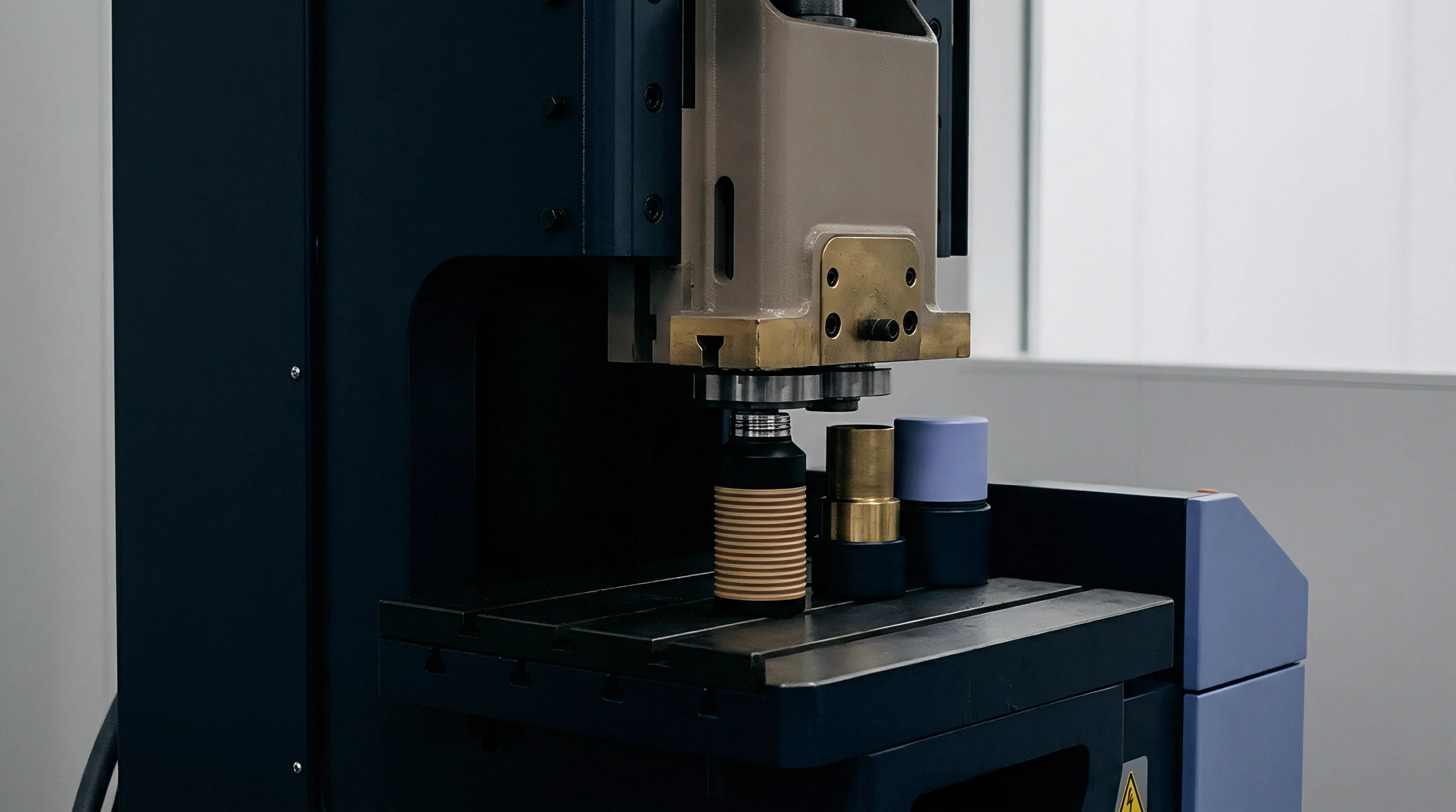
Thermal noise elevates dark current across silicon CMOS sensors even without illumination, and pixel-to-pixel variations create fixed-pattern noise across the array. Subtracting a calibrated dark frame from live production imagery strips out this pattern before defect-detection algorithms run.
Gain calibration scales individual pixel response values to uniform outputs under flat illumination. The mathematical matrix calculation follows a linear correction formula:
Corrected Output = (Raw Frame – Dark Frame) (Target Value / (White Frame – Dark Frame))
Calculations run directly on camera FPGAs in microseconds per line. At 100 kilohertz line rates, an 8K CMOS camera pushes over 800 megabytes per second, making onboard hardware correction essential for real-time processing.
| Processing Stage | Algorithm Complexity | FPGA Execution Time (µs) | Data Bandwidth Impact |
|---|---|---|---|
| Dark Current Subtraction | O(N) Vector Subtract | 1.2 | Zero Bandwidth Change |
| Flat-Field Gain Multiply | O(N) Pixel Multiply | 2.4 | Zero Bandwidth Change |
| Geometric Lens Unwarping | 2D Bilinear Spatial Lookup | 8.6 | Reduces Output Window Size 5% |
| Dynamic Contrast Equalization | Histogram Equalization | 14.1 | Expands Bit-Depth 8 to 12 Bit |

Adaptive Gain and Noise Subtraction
When substrates change color or opacity across product runs, fixed lighting either saturates sensors or loses low-contrast signals below the noise floor. Automatic gain routines adjust integration times and analog pre-amp levels on the fly using real-time image histograms.
System integrators must avoid several common calibration hardware and logic failure modes when deploying machine vision software for variable chemical webs:
- Uncompensated Illumination Thermal Drift leads to gradual intensity loss across a run, causing algorithms to misclassify clear base film as heavy chemical coating.
- Static Flat-Field Profile Reuse leaves old vignetting profiles active on newly installed lenses, creating edge-intensity artifacts and false margin alerts.
- Uncalibrated Spatial Distortion produces non-linear pixel scaling across the web, throwing off physical defect measurements by up to eight percent near the edges.
- Saturated Dark-Current Maps recorded under ambient light create dead-pixel voids that mask pinholes in opaque coatings.
Algorithmic software filtering cannot substitute for physical target recalibration when chemical coating batches change.


Scale

Roll-to-Roll Integration at High Line Speeds
At web speeds of 120 meters per minute and a target resolution of 20 microns per pixel, line-scan cameras must operate above 100 kilohertz. This compresses exposure times below 10 microseconds per line, where uncalibrated optical systems readily miss critical coating defects.
Shorter exposures starve sensors of light, and simply raising analog gain amplifies thermal noise alongside the actual signal. High-speed lines instead rely on Time Delay and Integration (TDI) sensors with 64 to 256 accumulating stages synchronized to web speed, increasing effective light collection 200-fold without motion blur.
| Calibration Routine | Execution Cycle | Line Downtime Per Cycle | Scrap Waste Generated (m) | Monthly Yield Cost Difference ($) |
|---|---|---|---|---|
| Manual Target Placement | Every 8 Hours | 18 Minutes | 360 | 14,400 |
| Automated Motorized Tile | Every 4 Hours | 45 Seconds | 15 | 1,800 |
| Continuous Inline Dual-Wavelength | Real-time Line Operation | 0 Seconds | 0 | 0 |
Commercial Impact of Uncorrected Sensor Drift
Thermal expansion flexes camera mounting frames during extended production runs. A shift of only a few micro-radians moves tracking points across a two-meter web by several pixels. Uncorrected mechanical drift skews edge detection, leading automated slitting blades to cut functional films outside dimensional tolerances.
On separator film lines processing 50,000 meters daily, uncorrected optical drift drives up false rejection rates and lets coating voids escape undetected. Inline, auto-calibrated vision systems bring false scrap below 0.05 percent of total roll volume.
Quality specifications require optical accuracy to be verified against traceable physical standards at full operating temperature before finished rolls receive sign-off.