Wave Soldering Thermal Profile Calibration after Extended Factory Shutdowns
Calibrating wave solder thermal profiles after extended shutdowns prevents barrel fill defects, dross contamination, and micro-ball bridging.


Soak
Preheat Thermal Lag in Cold Furnace Chambers
Thermal preheat zones in continuous wave soldering tunnels experience significant thermal shifts when restarting after extended downtime. Moisture penetrates refractory insulation linings, quartz heating elements, and forced-air plenum chambers during two-week or monthly plant shutdowns. When line technicians apply electrical power, the initial heat energy vaporizes absorbed water rather than raising tunnel air temperature.
This latent heat absorption drops top-side printed circuit board assembly surface temperatures by as much as eighteen degrees Celsius compared to baseline steady-state readings.
Infrared pyrometers and internal temperature sensors report false equilibrium during the first ninety minutes of operation. Heating element resistance changes across prolonged cold states, causing current draw variances that skew closed-loop proportional-integral-derivative controllers. The top-side heating glass tubes accumulate ambient shop dust during idle weeks.
This contamination reduces radiant thermal transfer efficiency until the debris burns off completely. Line operators who launch production immediately after digital temperature displays reach setpoint subject initial assembly batches to severe under-heating.
| Preheat Zone | Setpoint Temperature | Cold Start Surface Temp | Steady State Surface Temp | Thermal Variance |
|---|---|---|---|---|
| Zone 1 (Bottom IR) | 140°C | 112°C | 138°C | -26°C |
| Zone 2 (Forced Air) | 160°C | 141°C | 159°C | -18°C |
| Zone 3 (Top Forced Air) | 130°C | 118°C | 129°C | -11°C |
Failure to allow full thermal equilibrium degrades assembly quality across four distinct mechanical mechanisms. Solder paste and liquid flux vehicles require precise thermal ramp rates between 1.5 and 2.5 degrees Celsius per second to activate synthetic rosin compounds. Cold tunnel walls pull heat away from passing carrier frames.
Titanium conveyor chains expand non-uniformly when heated rapidly, creating track alignment issues that alter board clearance over flux spray nozzles.
Thermal ramp rates exceeding 2.5 degrees Celsius per second during cold restart induce thermal shock in multilayer ceramic capacitors.

Flux Activation Kinetics across Moisture Loaded Boards
Liquid flux application relies on accurate substrate temperatures to flash off solvent carriers before assemblies enter the molten wave. Alcohol-based and water-based flux systems behave differently when preheat zones run cold. Alcohol vehicles evaporate at lower thermal thresholds, but residual moisture left inside board vias during humid shutdown periods suppresses activation reactions.
Water-soluble organic acid fluxes require sustained top-side temperatures of 105 to 120 degrees Celsius to drive off water carriers completely.
When unevaporated water reaches the molten solder wave at 260 degrees Celsius, rapid phase change causes micro-explosions. Liquid solder splatters across the bottom side of the printed circuit board, depositing microscopic solder balls across fine-pitch surface mount pads. Solder micro-balls form bridges between adjacent conductor traces, causing short circuits that slip past simple visual inspection.
Liquid solvent trapped under heavy transformers or connector bodies prevents carboxyl acid compounds from stripping copper oxides from component leads. The resulting solder joints exhibit incomplete hole fill, pinholes, and voiding inside barrel walls.
A cold preheat profile leaves activator acids unreacted on the board surface. Residual active halides corrode copper traces over extended operational lifespans under humid ambient conditions. Factory managers monitoring post-shutdown yields frequently mistake this chemical failure for poor solder alloy purity.
The root cause remains uncalibrated preheat thermal absorption dynamics inside the tunnel chamber.
What thermal drift threshold forces a line technician to stop the wave conveyor entirely?
Pot

Solder Alloy Stratification and Dross Accumulation Rates
Molten tin-lead and lead-free alloys segregate into compositional layers when held at ambient or reduced setback temperatures over extended idle periods. Heavy element constituents like silver, copper, and bismuth settle toward the bottom of the reservoir tank, while lighter elements collect near the surface liquid plane. The pump impeller draws material from the lower middle zone, circulating off-ratio alloy mixtures through the nozzle chimneys until full mechanical agitation re-mixes the bath.
Surface oxidation accelerates during static thermal cycles. A thick layer of tin oxide and lead oxide dross blankets the liquid bath, trapping unreacted metal within a crusty skin. Impeller pumps forcing alloy through narrow wave generator nozzles encounter restricted flow channels when dross particles lodge inside internal baffles.
This obstruction alters fluid dynamics across both turbulent and smooth wave surfaces, creating height variations across the width of the conveyor path.
Solder pots standing idle for over two weeks accumulate localized oxides that skew wave height readings until three full dross skimming passes are completed.

Impurity Thresholds and Impeller Speed Verification
Dissolved copper content increases rapidly inside stationary solder baths when production lines restart after prolonged downtime. Residual copper wire strands, board trim, and dissolved component terminations settle into the sump during static holds. IPC-J-STD-001 mandates maximum allowable contaminant thresholds for operating solder baths.
Copper concentration exceeding 0.30 percent by weight raises the liquidus temperature of SAC305 alloy above its standard 217 degrees Celsius melting point, creating gritty solder joints and needle-like icicles on lead ends.
- Laminar Wave Sag ~ Pump motor belt slippage drops wave height by two millimeters, preventing full contact with deep hole-through leads.
- Copper Cross Contamination ~ Dissolution of board copper exceeding 0.30 percent weight raises melting points and forms brittle intermetallic compounds.
- Dross Inclusion Cratering ~ Oxidized surface skin drawn into the nozzle intake creates structural voids inside plated-through barrels.
- Intermetallic Thickness Spikes ~ Excessive solder dwell time inside an uncalibrated wave produces thick copper tin intermetallic layers that fail under mechanical shear testing.
Verification of pump motor speed require optical tachometer measurements directly on the driving shaft. Tachometer readouts on digital control panels reflect command voltage rather than physical revolution rates. Hardened flux residues on drive chains and worn shaft bearings decrease actual impeller rotation speed by four to eight percent.
Lower impeller speed collapses the standing wave height, causing incomplete solder fillet formation on trail-edge component leads.
A wave solder pot standing untouched for weeks yields clean fillets only after thorough skimming, complete thermal equilibrium, and compositional assay verification.

Profiling

Thermocouple Attachment Methods for Verification Assemblies
Direct contact thermal profiling provides the foundational data needed to calibrate tunnel settings after extended shutdowns. Engineers must construct dedicated golden profiling boards matching the exact layer count, copper weight, and component distribution of current production runs. Attaching thermocouples using standard polyimide tape yields inaccurate thermal readings because air gaps insulate the sensor bead from the board substrate.
High-temperature silver solder or conductive epoxy secures the wire bead directly to inner ground plane vias and high-thermal-mass component leads.
- Attach calibrated K-type thermocouples to four distinct thermal mass zones on a test assembly using high-temperature silver solder.
- Run the instrumented board through the wave solder tunnel without applying flux to verify pure thermal conveyor dynamics.
- Record thermal dwell times above liquidus and compare against baseline profiles established prior to shutdown.
- Adjust individual heating zone setpoints until temperature differentials across the board surface drop below five degrees.
Thermocouple wire placement targets four distinct physical locations on the test assembly. Position one sits on a thin trailing corner trace to measure maximum thermal ramp rate. Position two attaches to an inner pin of a heavy multi-row connector representing high heat sink capacity.
Position three connects to a central plated-through barrel to evaluate vertical solder fill potential. Position four sits on the leading edge bottom mask surface to measure immediate thermal impact upon contacting the molten wave.
Contracts specifying IPC-A-610 Class 3 acceptance standard compel fresh thermal profiling runs after any uninterrupted equipment outage exceeding seventy-two hours.

What Temperature Spans Indicate Adequate Flux Activation?
Lead-free alloys demand strict window management between flux activation temperatures and peak thermal exposure. SAC305 requires top-side preheat temperatures between 110 and 130 degrees Celsius prior to wave contact. Lower temperatures leave liquid flux vehicles unevaporated, while higher temperatures burn off active acid compounds before assemblies reach the solder nozzle.
Bottom-side board surface temperature must reach 120 to 140 degrees Celsius immediately before entering the first wave.
| Parameter | Minimum Target | Maximum Target | Process Impact if Exceeded |
|---|---|---|---|
| Preheat Ramp Rate | 1.0°C / sec | 2.5°C / sec | Thermal shock to ceramic chip capacitors |
| Top-side Board Temp | 110°C | 130°C | Flux vehicle burnout or incomplete drying |
| Wave Dwell Time | 2.5 seconds | 4.5 seconds | Pad lifting or intermetallic layer growth |
| Peak Temperature | 255°C | 265°C | Laminate delamination and component damage |
| Cooling Ramp Rate | 2.0°C / sec | 6.0°C / sec | Solder joint cracking and micro-voiding |
Total contact dwell time across both turbulent and laminar waves must hold between 2.5 and 4.5 seconds. Dwell time under 2.5 seconds fails to supply sufficient energy to drive solder up complex plated-through barrels, yielding Class 2 fill defects. Dwell time over 4.5 seconds dissolves surface copper, degrades glass-epoxy laminate resin, and grows brittle intermetallic layers that crack during vibration testing.
Deploying an uncalibrated thermal profile after a prolonged plant outage causes immediate batch-wide hole-fill failures, widespread solder bridging, and costly manual board scrap.

Drift
Conveyor Velocity Slip and Mechanical Wear
Conveyor drive systems suffer mechanical alteration during extended plant shutdowns. Lubricants inside drive gearbox assemblies thicken, increasing drag on drive motors when power turns back on. Finger-type conveyor chains collect hardened flux resin splatters that lock pivot joints, creating localized chain stretching under load.
This non-uniform resistance causes subtle linear speed fluctuations across the length of the soldering tunnel.
A conveyor set to 1.2 meters per minute under nominal conditions may run at 1.08 meters per minute during cold restart, shifting to 1.24 meters per minute once mechanical components warm up. This velocity variance directly alters solder wave contact dwell times. A twelve percent drop in conveyor speed increases thermal exposure in the wave by nearly half a second, overheating delicate surface mount components on the bottom side of the board.
- Conveyor Speed Tachometer Validation ~ Compare digital encoder output against manual optical measurement over two meters of track.
- Flux Specific Gravity Check ~ Titrate water-based or alcohol-based flux to verify solvent ratio prior to tank top-up.
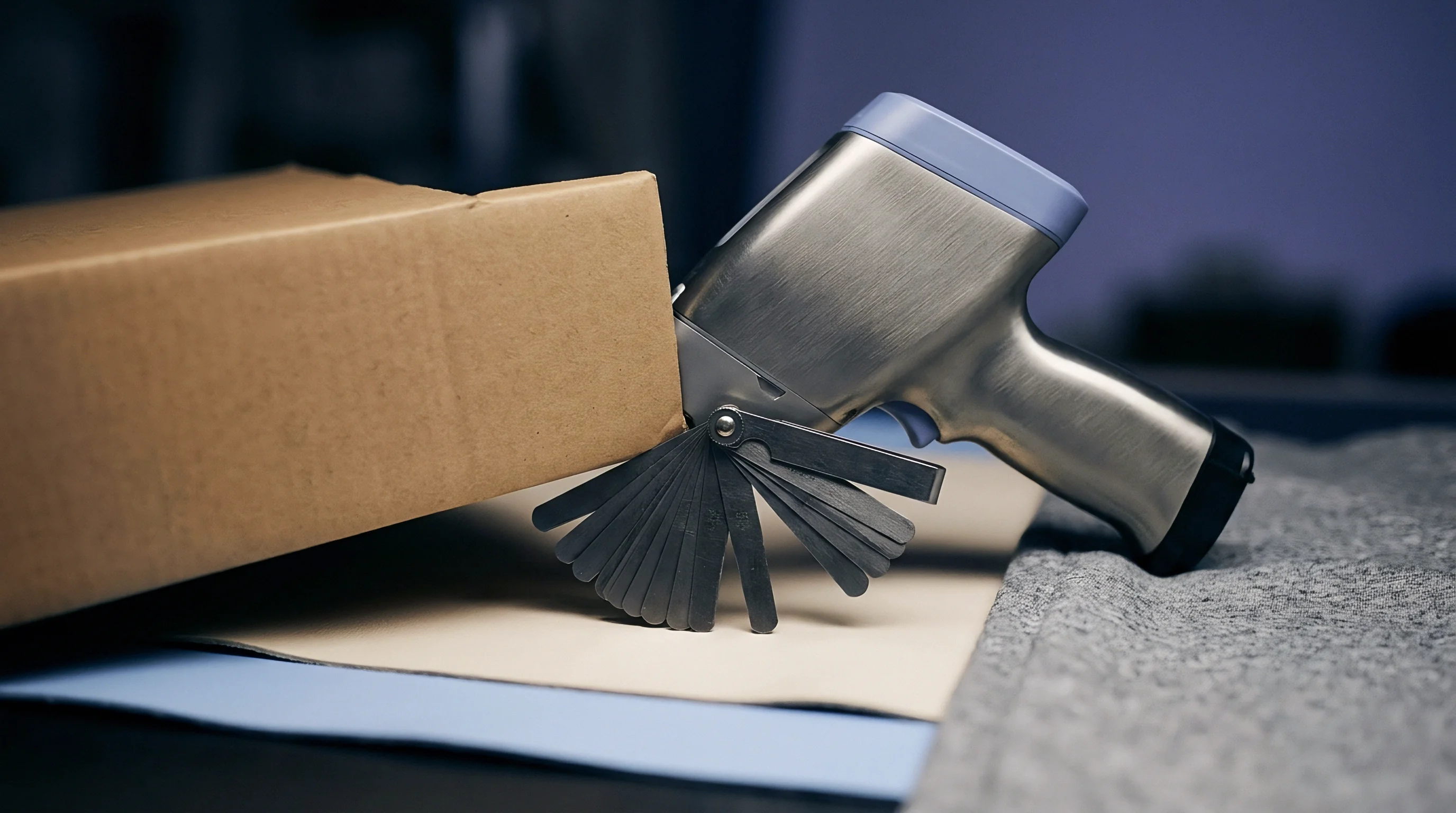
- Air Knife Clearance Calibration ~ Measure distance from board bottom edge to air knife nozzle with feeler gauges.
- Finger Cleaner Fluid Level Audit ~ Verify automatic conveyor finger cleaning fluid pump pressure to prevent flux resin transfer.

Flux Specific Gravity and Solvent Loss Stabilization
Liquid flux reservoirs stored in spray applicator systems undergo evaporation shifts during factory idle periods. Solvent vehicles evaporate through tank breathers, raising active chemical concentrations above specification. High specific gravity flux deposits excessive solids on assembly surfaces, leaving sticky residues that attract dust and cause leakage currents in high-voltage circuit paths.
Recirculating foam fluxers experience rapid degradation when air stones clog with dried rosin crystals. Clogged stones produce uneven foam heads with large air pockets, causing localized dry spots across passing assemblies. Spray fluxers utilizing ultrasonic nozzles require piezoceramic element testing after shutdowns.
Dried flux inside fluid delivery lines restricts flow rates, causing uneven spray deposition patterns across the board width.
Factory maintenance crews often claim that pre-shutdown calibration values remain perfectly valid because no mechanical adjustments were made during the idle period.

Rework
Scrap Yield Economics and Board Touch up Costs
Skipping thermal calibration after an extended plant shutdown introduces financial loss through post-solder defect inspection, manual touch-up labor, and component replacement scrap. Consider a baseline production run of 10,000 double-sided assemblies containing through-hole connectors and surface mount components. Launching production without profile re-qualification under cold tunnel conditions typically yields a initial defect rate of 4.2 percent across all solder joints, primarily driven by insufficient barrel fill and bridging.
Manual touch-up costs require detailed financial calculation. An IPC-certified operator takes an average of 4.5 minutes to inspect, re-flux, heat, and repair a defective through-hole joint under a microscope. At a fully burdened operator labor rate of 38 USD per hour, touch-up labor costs 2.85 USD per defective joint.
With an average of three defective joints per rejected assembly across 420 failed units, total direct touch-up labor reaches 3,591 USD per batch.
| Production Volume | Uncalibrated Defect Rate | Rework and Scrap Cost | Calibration Run Expense | Net Financial Difference |
|---|---|---|---|---|
| 1,000 units | 4.2% | 855 USD | 420 USD | + 435 USD saved |
| 5,000 units | 4.2% | 4,275 USD | 420 USD | + 3,855 USD saved |
| 10,000 units | 4.2% | 8,550 USD | 420 USD | + 8,130 USD saved |
| 25,000 units | 4.2% | 21,375 USD | 420 USD | + 20,955 USD saved |
Material scrap costs multiply these financial losses. Thermal shock during uncalibrated cold preheating cracks multilayer ceramic capacitors in 0.8 percent of production units. Damaged capacitors exhibit high-leakage failures during final functional testing, forcing complete board disposal if inner-layer shorting occurs.
Replacing a scrapped bare board loaded with active integrated circuits carries an average unrecoverable cost of 48 USD per unit. Across 80 scrapped assemblies in a 10,000-unit batch, component material loss equals 3,840 USD.
Profile re-qualification expenses require three hours of line downtime, two dummy test boards, and engineer labor totaling 420 USD. Investing 420 USD in calibration before starting production eliminates 8,550 USD in combined rework labor and scrap loss per 10,000 assemblies shipped. Solder line management directly dictates profitability by enforcing mandatory thermal calibration routines prior to releasing extended-shutdown production lines.
Line downtime during profile calibration costs less than replacing thermal shock damaged ball grid arrays during functional testing.
Purchase specifications incorporating mandatory thermal profiler run logs prior to lot acceptance bind the manufacturing facility to perform complete line calibration before running high-reliability product batches.