Soft Tooling Selection and Amortization for Micro Runs
Soft tooling selection balances rapid lead times against progressive cavity wear, requiring direct NRE payment and scrap inflation modeling for micro runs.

Geometry
Polymer Shrinkage and Cavity Compliance
Part fidelity depends heavily on volumetric contraction when transitioning from CAD models to cut cavities. As thermoplastics cool, crystalline structures pack together in predictable ways. Amorphous polymers like polycarbonate shrink between 0.5 percent and 0.7 percent by volume, whereas semi-crystalline resins such as polypropylene or nylon 66 show volumetric shrinkage between 1.5 percent and 2.5 percent.
When machining cavities in rigid metals like AL7075-T6 or P20 steel, CNC toolpaths scale directly from the resin manufacturer’s published isotropic shrinkage coefficient. Soft tooling makes this math harder, introducing elastic deflection and uneven thermal expansion under injection pressures.
Room Temperature Vulcanizing silicone molds used in polyurethane casting expand as exothermic cross-linking heats the liquid resin, driving core temperatures up to 80 degrees Celsius. Silicone carries a linear thermal expansion coefficient near 3 x 10^-4 per degree Celsius ~ ten times higher than aluminum. Under liquid vacuum injection, soft mold walls bow outward, then contract as the reaction cools.
Part walls thicker than four millimeters hold heat long enough to distort adjacent mold walls, leaving sink marks on external surfaces opposite thick internal ribs. Designing for elastomeric tooling means maintaining uniform wall thickness across every cross-section to control differential thermal mass.
Rigid aluminum bridge tooling tolerates injection pressures up to 1,200 bar without wall compliance, but machining the cavity still requires careful attention to geometry. Rib thickness needs to stay between 50 percent and 60 percent of the adjacent nominal wall. Going past that ratio pulls material away from the outer skin during cooling, causing surface depressions.
Choosing soft tooling ultimately means fitting part geometry to material strength limits. In micro runs of 50 to 2,000 units, geometric errors hit harder because tight budgets leave no room for secondary machining passes to re-cut dimensions.
Draft Angles for Soft Matrix Stripping
Vertical sidewall relief dictates how much physical force demolding takes. Steel production tooling uses automatic ejector pins, hydraulic core pulls, and mechanical slides to strip deep features. Soft tooling relies far more on manual labor ~ technicians flexing elastomeric mold halves or prying parts out of aluminum cavities with copper picks.
Skimping on draft builds up friction quickly, leaving scuffed surfaces, warped parts, or torn silicone.
Silicone RTV molds can handle zero-degree draft on shallow features thanks to matrix elasticity ~ the elastomer simply stretches around light undercuts during stripping. Deep vertical cores, however, need positive relief to keep the tool from wearing out prematurely. A one-degree draft per side serves as the baseline for vertical features deeper than 25 millimeters, while deep ribs or textured surfaces require another 0.5 degrees per side for every 25 micrometers of texture depth.
When casting higher shore hardness polyurethanes, draft angles have to match standard injection molding rules to prevent tearing delicate internal features.

Ejection Forces in Elastomeric Cavities
Hand stripping relies on flexing the rubber boundary rather than firing automated ejector pins. Vacuum seals form easily between smooth plastic faces and silicone cavity walls as the part separates. Technicians pop compressed air through micro-nozzles along the parting line to break that suction; without air assist, demolding forces concentrate on thin feature transitions, tearing fine silicone detail and ruining the cavity in fewer than fifteen cycles.
Aluminum soft tooling relies instead on mechanical ejector plates driven by the press hydraulics. Since 7075-T6 aluminum has a lower yield strength than hardened steel, ejector pins require broader contact heads. Narrow pins risk punching straight through warm, semi-rigid plastic or denting soft aluminum cavity floors under repeated cycling.
Parting Line Degradation in Flexible Molds
Repeated mechanical flexing eventually breaks down the mold along its joint line. Silicone RTV tooling consists of split blocks clamped inside wooden or aluminum support frames. Over repeated cycles, polyurethane casting resins ~ loaded with aggressive amine catalysts and reactive ISOCYANATE groups ~ attack the silicone polymer chains.
This chemical embrittlement strips the elastomer of its flexibility, causing parting line edges to chip away under vacuum clamping pressure.
As the mold seam degrades, flash gets progressively thicker. Early castings stay below 0.05 millimeters of micro-flash along the parting line, but by cycle thirty, edge breakdown widens the gap beyond 0.3 millimeters. Trimming that extra material by hand adds direct labor to every part in a short run.
Once flash creeps past drawing tolerances, the mold requires either repair with liquid silicone patches or retirement. Aluminum prototype molds hold up against chemical attack, but their parting lines flash if hydraulic clamping misaligns or pinches stray debris. Small plastic flakes squished between soft aluminum parting faces leave permanent dents, producing constant flash until the surfaces are cleaned up on a micro-milling machine.
What structural modifications can preserve geometry when scaling a soft tool past its nominal cycle limit?
Mold
Substrate Material Limits and Expected Pull Count
Substrate choice sets upfront NRE expenditure and long-term part stability. Tooling decisions for micro runs always balance total shot life against machining labor. Silicone RTV molds require minimal initial capital, but degrade after 25 to 50 pulls.
High-density polyurethane casting resins attack the silicone matrix, pulling out plasticizers and embrittling fine detail, while glass-filled resins accelerate mechanical wear to drop functional tool life below twenty pulls. Switching to soft aluminum 6061-T6 extends tool life to between 1,500 and 3,000 injection shots for unfilled polypropylene or ABS. Tougher 7075-T6 aluminum handles 10,000 to 20,000 shots, bridging the gap between quick prototypes and production steel dies.
Direct 3D-printed photopolymer inserts offer quick turnaround for micro-injection molding. DLP and SLA resins can print complete cavity inserts in under twelve hours. When reinforced with metallic fillers, printed inserts tolerate clamping pressures up to 800 bar and thermal spikes up to 200 degrees Celsius.
Even so, mechanical strength limits them to 50 to 200 shots because abrasive resins chew through gate areas and sharp corners. Pre-hardened NAK80 steel provides 30 to 40 HRC hardness and survives up to 50,000 shots without heat treatment. Because NAK80 machines cleanly on high-speed CNC centers without post-quench grinding, it works as a practical middle ground for higher-volume micro runs.
| Tooling Material | Initial NRE Cost (USD) | Lead Time (Days) | Expected Shot Life | Maximum Operating Temp (°C) | Dimensional Tolerance (mm) |
|---|---|---|---|---|---|
| RTV Silicone (Addition Cure) | $800 – $1,500 | 3 – 5 | 25 – 50 | 80 | ±0.15 |
| Photopolymer 3D Printed Inserts | $400 – $1,000 | 1 – 2 | 50 – 200 | 200 | ±0.10 |
| Aluminum 6061-T6 | $3,500 – $6,000 | 7 – 10 | 1,500 – 3,000 | 280 | ±0.05 |
| Aluminum 7075-T6 | $5,000 – $9,000 | 10 – 14 | 10,000 – 20,000 | 320 | ±0.03 |
| NAK80 Pre-Hardened Steel | $8,000 – $15,000 | 14 – 21 | 50,000 – 100,000 | 400 | ±0.015 |
Thermal Dissipation Differences across Cavity Inserts
Heat extraction drives both cycle time and thermal stress distribution across injection tooling. Aluminum 7075-T6 has a thermal conductivity of 130 W/m·K ~ nearly four times that of P20 tool steel at 29 W/m·K. Because aluminum absorbs and releases heat quickly, cooling line layouts can be simplified without sacrificing cycle speed. That rapid dissipation cuts overall cycle times by 20 percent to 30 percent on thick-walled parts.
Silicone tooling requires a minimum six-hour room temperature cure cycle between liquid resin castings to prevent cumulative thermal buildup from exothermic reaction heat.
In printed photopolymer inserts, low thermal conductivity (0.2 W/m·K) drags out cycle times. Thermoplastic injected at 230 degrees Celsius stays molten against printed cavity walls because the tool cannot pull heat away efficiently. Operators have to lengthen dwell and cooling phases from 15 seconds to well over 90 seconds per shot.
Cycling printed inserts too quickly softens the surface, builds up resin residue, and triggers catastrophic compressive cracking, so cavity faces need a compressed air blast between shots to keep surface temperatures under control.
Can Tool Cavity Modifications Extend Soft Die Life?
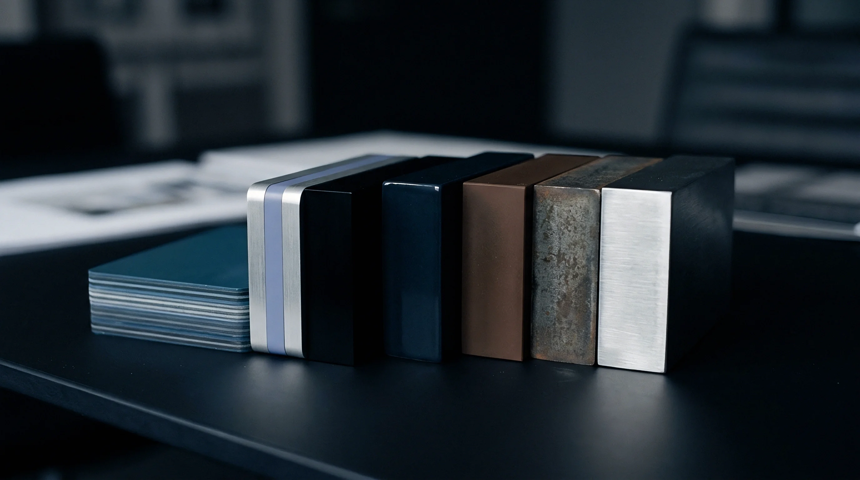
Getting more life out of soft tooling usually means reinforcing high-wear areas rather than building a full steel mold. Sprue bushings, runner intersections, and main gates take the brunt of fluid erosion and shear stress. Sinking P20 steel gate inserts into aluminum core plates prevents gate washing and holds crisp edge geometry across tens of thousands of cycles.
Surface treatments offer another way to protect soft metals against mechanical wear. Anodizing an aluminum cavity builds an oxide layer 25 to 50 micrometers thick, with hard coat anodizing pushing surface hardness above 60 HRC to stand up to glass-filled resins. Electroless nickel deposits an even 10 to 20 micrometer shell across intricate cavity features, shielding the underlying alloy from corrosive fluoropolymers or flame-retardant additives.
These coatings have to go on before the tool ever runs; plating after the fact cannot rebuild eroded geometry.
Tool failure modes vary by material matrix:
- Gate Washing occurs when high-velocity resin erodes soft aluminum or printed plastic edges, widening gate dimensions and leaving long gate stubs.
- Cavity Compression takes place when excessive clamp tonnage deforms soft aluminum parting lines, inducing permanent sink and edge misalignment.
- Thermal Cracking appears on photopolymer insert surfaces subjected to rapid heating and cooling cycles without long cooling delays.
- Silicone Embrittlement develops as amine catalysts extract plasticizers, turning soft elastomer brittle and causing surface tearing.
- Ejector Pin Bending happens when soft pin guides expand under lateral forces, causing pins to jam or score cavity walls.
Aluminum tools can run cold without internal heating channels when shot volumes stay below five hundred units per shift.

Schedule
Thermal Equilibrium and Cycle Time Modulation
Machine stability relies on reaching steady thermal equilibrium across the mold plate assembly. Where hardened steel tooling relies on conformal cooling channels and industrial chillers to keep cavity temperatures within a two-degree window, micro-run soft tools usually rely on simple drilled water lines or external fans to keep costs down. Aluminum tooling absorbs thermal spikes quickly, but its dimensions shift whenever ambient shop temperatures drift or press cadence stutters.
Interrupting the injection rhythm destroys thermal equilibrium, producing part weight swings that breach statistical process control limits.
Short-run shops across Guangdong and Zhejiang manage thermal drift by tweaking cycle times during production. Operators stretch cooling cycles over the first twenty shots while the aluminum core warms to its 50 to 60 degrees Celsius operating range. Once core temperatures settle, they drop the dwell time to maximize throughput.
If the machine stops for routine maintenance or hopper refills, the mold cools off, forcing the operator to purge and scrap the first five shots upon restart. Production schedules have to factor in these thermal stabilization scrap allowances instead of assuming 100 percent yield from shot one.
ISO 2859-1 sampling plans applied to micro-run soft tooling require elevated inspection levels because part dimensions drift continuously as soft mold cavities degrade.
Manual De-Molding Cadence on Short Production Lines
Manual labor dictates throughput when running soft silicone molds or prototype aluminum tooling without automated ejection. Silicone RTV casting requires a technician to manually open the mold, pull flexible cores, wipe cavity faces, spray release agent, and reset loose pins. That cycle takes four to eight minutes per part, compared to twelve seconds on an automated injection press.
Scheduling a run of 500 polyurethane cast parts cannot rely on standard machine formulas ~ output depends entirely on bench staffing and station ergonomics.
Micro-run production planning follows strict sequence protocols to preserve tooling integrity:
- Preheat aluminum mold halves in an external oven to 60 degrees Celsius prior to mounting on the platen to minimize thermal shock from molten resin injection.
- Purge injection barrel with low-MFI polypropylene compound to remove residual high-temperature resins that could burn soft aluminum runner channels.
- Set machine clamp tonnage to the lowest pressure that prevents flash, avoiding excessive compressive forces on soft parting lines.
- Apply non-silicone mold release agent to cavity surfaces every five cycles to prevent polymer adhesion on soft metal faces.
- Inspect ejected parts under five-times magnification every ten shots to check for parting line flash, gate erosion, or ejector pin denting.
- Log cavity dimensions with digital calipers every fifty shots to track progressive material compression or thermal expansion trends across the production run.
Supplier Capacity Shifts between Prototype and Production
Tier-two suppliers build their operations around dedicated production lanes. High-volume plants optimize for long runs on heavy 300-ton to 1,000-ton injection presses, but clamping an aluminum micro-run mold into a high-tonnage machine creates clear problems. Heavy clamping crushes soft aluminum parting lines, and large-press setup fees destroy the cost advantages of soft tooling.
Short runs belong on low-tonnage, quick-change hydraulic or electric presses in the 30 to 120 ton range.
Delays happen when suppliers bounce micro runs between prototype shops and production floors. Prototype shops have skilled techs but often lack automated resin drying, causing moisture voids in molded parts. Production floors have automated material handling but relegate short runs to low-priority fill-in work between high-volume jobs.
Buyers require suppliers to lock micro-run jobs onto dedicated low-tonnage presses with fixed shift assignments to prevent teardowns and hold delivery schedules.
| Tooling Setup | Batch Size (Units) | Setup Time (Hours) | Average Cycle Time | Target Daily Yield | Scrap Rate Expectation |
|---|---|---|---|---|---|
| RTV Silicone (Manual Vacuum Cast) | 50 | 1.0 | 360 seconds | 40 – 60 parts | 8% – 12% |
| Printed SLA Inserts (Benchtop Press) | 150 | 2.5 | 75 seconds | 200 – 300 parts | 5% – 8% |
| Aluminum 6061 (100-Ton Semi-Auto) | 500 | 3.0 | 28 seconds | 800 – 1,200 parts | 3% – 5% |
| Aluminum 7075 (100-Ton Full-Auto) | 2,500 | 4.0 | 18 seconds | 1,800 – 2,500 parts | 1.5% – 3% |
| NAK80 Soft Steel (150-Ton Full-Auto) | 10,000 | 5.0 | 14 seconds | 3,000 – 4,500 parts | 0.8% – 1.5% |
Failing to stabilize thermal conditions during press setup causes bulk dimensional drift, throwing entire short-run batches out of tolerance before first-piece inspection even starts.

Accounting
Piece Price Loading versus Upfront Tooling NRE
Commercial terms for micro-run tooling follow two main paths: direct non-recurring engineering (NRE) charges or piece-price amortization. Direct NRE mandates that the buyer pay 100 percent of tool fabrication upfront before sampling starts. Amortization folds tooling expense into individual unit invoices, letting buyers spread capital out across production deliveries.
On short runs, however, supplier-financed amortization carries heavy hidden risk premiums.
Suppliers pad amortized piece prices to cover the risk of truncated production runs. Amortizing a $6,000 aluminum mold across a projected 2,000-unit order works out to a baseline tool cost of $3.00 per unit. In practice, suppliers stack a 40 percent to 60 percent risk markup onto that fee, billing $4.50 to $5.00 per unit to guard against early cancellation.
If the run cuts off at 500 units, machining costs remain unrecovered unless minimum order volumes or explicit payback penalties back up the contract.
Scrap Rate Inflation and Degradation Curves
Scrap rates on micro runs rarely stay flat. Standard planning models frequently assume a steady 2 percent defect rate across the whole job, but soft tools undergo continuous dimensional drift, thermal fatigue, and parting line wear that push scrap higher as shot counts build up.
A 1,000-unit run on an unhardened 6061 aluminum mold illustrates the progression well. Over the first 100 shots, scrap averages 5 percent while thermal conditions stabilize and gates are tuned. From unit 101 to 700, scrap settles down to a steady 1.5 percent.
Past unit 700, parting line wear and ejector pin scoring force scrap up to 6 percent, and the final 100 units can see scrap top 12 percent as flash exceeds allowable tolerances. Accurate landed unit costs depend on factoring these rising scrap curves directly into initial payback models.
Tooling amortization schedules must decouple non-recurring engineering costs from piece-part production prices to prevent compounding supplier risk markups on micro-run orders.
Break Even Thresholds across Tooling Materials
Selecting a tooling substrate comes down to modeling total landed cost against volume. The cost equation balances NRE fees, raw material prices, press operator labor, and scrap allowances. RTV silicone requires low upfront NRE ($1,200) but drives unit costs to $25.00 due to costly resins and slow manual cycle times.
Hardened P20 steel demands steep initial NRE ($25,000), but pushes unit costs down to $1.20 through rapid automated cycling and minimal scrap.
Total cost crossover points establish clear economic operating windows. Silicone casting provides the lowest landed cost under 80 units. Photopolymer 3D-printed inserts win out between 80 and 300 units.
Aluminum 6061-T6 holds the advantage from 300 to 2,500 units, while aluminum 7075-T6 leads from 2,500 to 15,000 units. Beyond 15,000 units, production steel tooling amortizes cleanly, undercutting soft metals on landed piece price.
| Production Volume | RTV Silicone Casting | Printed SLA Mold Inserts | Aluminum 6061 Tooling | Aluminum 7075 Tooling | P20 Steel Hard Tooling |
|---|---|---|---|---|---|
| 50 Units | $2,450 ($49/unit) | $3,100 ($62/unit) | $5,750 ($115/unit) | $8,250 ($165/unit) | $26,200 ($524/unit) |
| 250 Units | $7,450 ($29.80/unit) | $5,850 ($23.40/unit) | $7,950 ($31.80/unit) | $10,250 ($41.00/unit) | $27,900 ($111.60/unit) |
| 1,000 Units | $26,200 ($26.20/unit) | $21,500 ($21.50/unit) | $10,800 ($10.80/unit) | $12,850 ($12.85/unit) | $29,500 ($29.50/unit) |
| 5,000 Units | N/A (Tool Exhausted) | N/A (Tool Exhausted) | $24,500 ($4.90/unit) | $21,250 ($4.25/unit) | $34,200 ($6.84/unit) |
| 20,000 Units | N/A (Tool Exhausted) | N/A (Tool Exhausted) | N/A (Tool Exhausted) | $48,500 ($2.43/unit) | $46,500 ($2.33/unit) |
Evaluating these dynamics requires modeling amortization profiles by combining setup overhead, cavity maintenance allocations, and scrap adjustments across target runs. Consider a 1,500-unit micro run of a complex medical housing. Upfront aluminum 7075 tooling NRE costs $7,500.
Raw material cost per part equals $2.20. Machine press time charges equal $4.00 per unit, while post-processing trimming adds $1.50 per unit. Baseline scrap averages 3 percent, adding $0.23 per part.
Total per-unit cost equals $7.93. Adding the amortized NRE fee of $5.00 yields a landed unit cost of $12.93. If the run expands to 5,000 units, the amortized NRE fee drops to $1.50, pulling the landed unit cost down to $9.43.
Soft tooling triggers non-refundable engineering charges whenever design revisions alter cavity dimensions beyond simple metal-safe shaving limits.
Amortizing soft tooling costs directly into the piece price appears to save customer capital, but suppliers often increase the base unit charge by 40 percent to cover their own downside exposure on unscheduled tool failures.

Contract
Tool Ownership and Ex-Factory Removal Terms
Cross-border contracts must clearly assign physical and intellectual property rights for soft tooling. Chinese manufacturing suppliers typically treat prototype and short-run tooling built in their own shops as factory property unless contract language explicitly says otherwise. Silent contracts allow suppliers to retain physical possession of molds, locking buyers into ongoing part orders.
If a buyer tries to shift tooling to another facility, the supplier can refuse ex-factory release or demand extra design fees.
Unambiguous terms establish buyer ownership immediately upon payment of the initial NRE invoice. Contracts must specify that soft tooling remains the sole property of the buyer, extending to all CAD geometry files, CNC toolpaths, core plates, cavity inserts, ejector plates, and custom hot-runner assemblies. Language should explicitly give the buyer or their designated freight representative the right to inspect, audit, and remove tools from the factory within 24 hours of written notice without exit fees or penalties.
Shot Life Guarantees and Refurbishment Liabilities
Soft tooling contracts require explicit shot life thresholds paired with mandatory supplier refurbishment obligations. While high-volume steel tooling agreements typically feature 500,000-shot or 1,000,000-shot guarantees, soft tooling contracts need realistic, material-specific thresholds. A contract specifying an aluminum 7075-T6 mold, for instance, should guarantee 10,000 acceptable parts built to print.
Commercial supply contracts must define soft tooling yield thresholds in written engineering specifications to bind supplier repair obligations directly to physical part tolerances.
If an aluminum mold suffers cavity cracking, gate erosion, or parting line collapse before meeting its guaranteed shot count, the supplier must repair or remake the tool at their own expense within ten calendar days. Refurbishment terms need to cover all labor, CNC machining, EDM wire erosion, polishing, and re-plating necessary to restore original cavity dimensions. Contracts should also stipulate that downtime costs caused by premature tool failure are deducted directly from outstanding component invoices.
Defect Allocation at End of Tooling Life
Assigning financial liability for bad parts means separating process mistakes from natural tool wear. As a soft tool nears the end of its functional life, quality degrades rapidly. Factories frequently attempt to ship out-of-tolerance parts toward the end of a short run, arguing that tool wear excuses dimensional drift.
Buyers need clear, enforceable dimensional and visual quality limits that apply through the final shot of the contract.
Contracts specify that components failing drawing tolerances remain non-conforming regardless of tool age or shot count. If a soft tool degrades before completing the agreed order, the supplier bears full financial responsibility for making replacement tooling. Formal tool retirement clauses mandate that suppliers issue written notification once tool wear consumes 80 percent of allowable drawing tolerances.
That notice triggers a mandatory review where the buyer can approve soft tool refurbishment, authorize a paid rebuild, or issue engineering deviation waivers before production continues.
The standard mold retention and maintenance clause states: “All prototype and short-run tooling, including aluminum cores, cavity inserts, ejector sets, and auxiliary components paid for under NRE Invoice , shall remain the exclusive property of the Buyer. The Supplier shall maintain such tooling in functional condition at Supplier’s sole expense for the duration of the guaranteed shot count of units, and shall release the tooling for ex-factory transit within twenty-four hours of written demand by the Buyer without assertion of possessory liens or exit surcharges.”