Tool Steel Grade Selection and Cavity Shrinkage Tolerances
Selecting tool steel grades for precision cavities requires balancing grain direction, heat treatment distortion, and alloy verification to hold tight part tolerances.


Grain
Forging reductions and rolling imprint a distinct directional texture across alloy tool steel blocks. When core and cavity inserts are carved from heavy forged stock, they undergo anisotropic dimensional shifts across thermal cycles. Carbides in the steel matrix align along the primary direction of mill hot-working.
As polymer melt fills the cavity under high pressure, heat conducts unevenly along orthogonal axes, with transverse axes exhibiting greater volumetric contraction than longitudinal axes relative to the rolling direction. Treating tool steel as an isotropic solid therefore builds systematic dimensional error into cavity calculations before cutting begins.
Dimensional stability depends directly on steel grade selection, which requires matching the metallurgical structure of the core to the shrinkage profile of the target resin. Amorphous resins like polycarbonate contract uniformly, typically between 0.5 percent and 0.7 percent. Semi-crystalline polymers like polybutylene terephthalate or polyphenylene sulfide show non-isotropic shrinkage from 1.2 percent to 2.4 percent, heavily governed by local shear flow and cooling rates.
Sinking a semi-crystalline cavity into steel with pronounced carbide anisotropy magnifies distortion across long spans. In Chinese injection molding operations, toolmakers frequently size cavities against baseline manufacturer shrinkage tables rather than empirical measurements taken from physical cores.
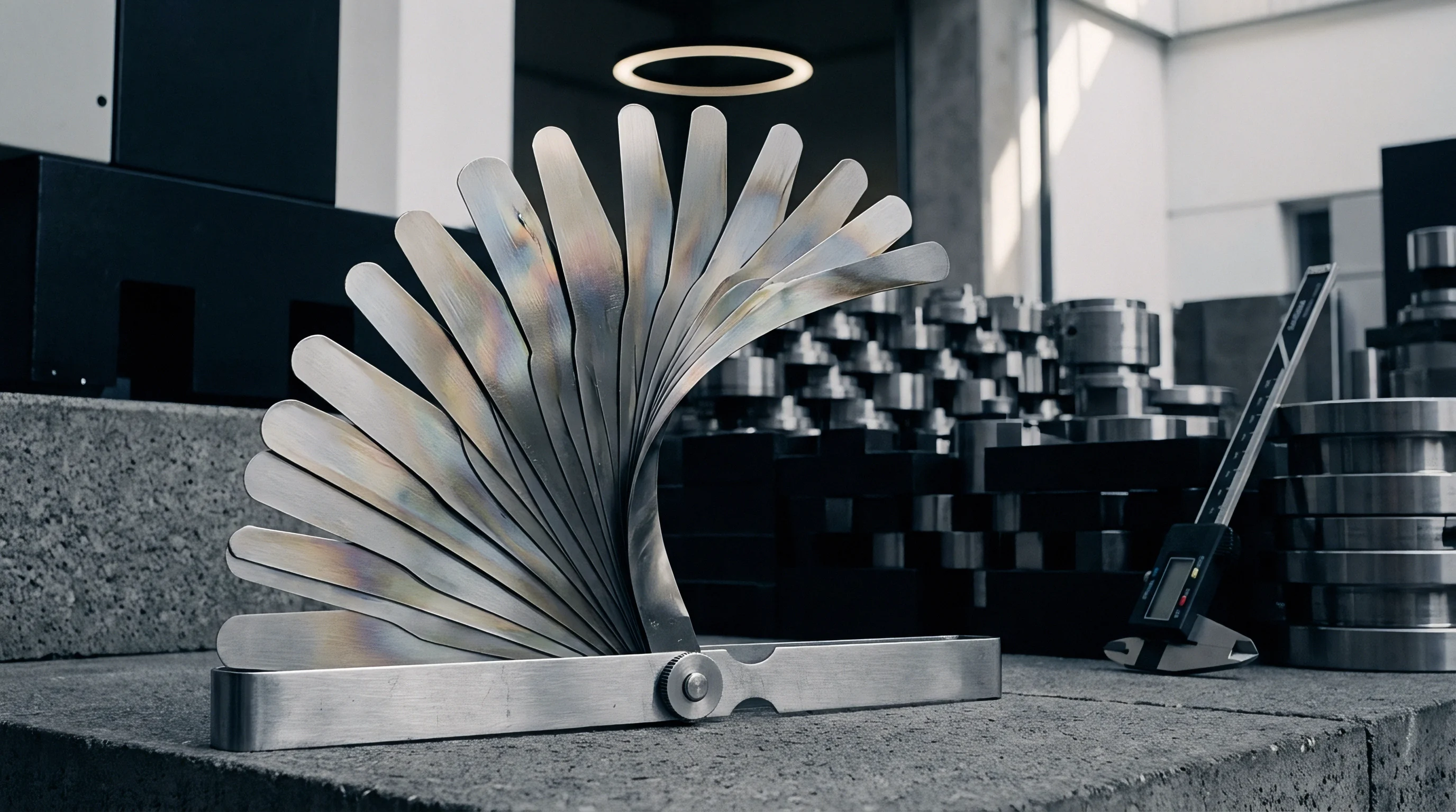
Isotropic Dimensional Drift in Tool Cavities
Accurate core sizing depends on tight thermal expansion matching between the mold cavity block and the molded part during ejection. Ingot-cast tool steel grades display heavy carbide segregation toward the center of large cross-sections, which skews the local coefficient of thermal expansion across the block. Premium grades refined through electroslag remelting produce a finer grain microstructure with uniform three-dimensional carbide distribution, eliminating macro-segregation and ensuring consistent expansion throughout the insert.
Tool steel subjected to electroslag remelting exhibits isotropic dimensional variations below 0.02 millimeters per 100 millimeters of core length under standard thermal cycles.
Carbide banding directly alters plastic contraction behavior. Standard pre-hardened AISI P20 (DIN 1.2311 or GB 3Cr2Mo) develops a banded ferrite-carbide structure as it air-cools after rolling. Machining deep cavity geometry across these bands exposes alternating layers of varying micro-hardness, which causes tool deflection to fluctuate and leaves microscopic stepping along draft walls.
This micro-stepping increases ejection resistance, requiring higher pack pressures that drive post-molding warpage and blow through cavity tolerance budgets.
| Steel Grade Standard | Process Method | Hardness Range (HRC) | Thermal Expansion (10^-6/K) | Transverse-Longitudinal Anisotropy Ratio | Target Polymer Shrinkage Band |
|---|---|---|---|---|---|
| AISI P20 (1.2311) | Conventional Ingot | 28 to 32 | 12.8 | 1.45 | 0.4% to 0.8% (Amorphous) |
| AISI H13 (1.2344) | Electroslag Remelting | 46 to 52 | 11.9 | 1.08 | 1.0% to 2.2% (Semi-Crystalline) |
| AISI S136 (1.2083) | Electroslag Remelting | 48 to 54 | 10.6 | 1.05 | 0.5% to 1.8% (Corrosive/Optical) |
| NAK80 (Pre-hardened) | Precipitation Hardened | 37 to 43 | 11.3 | 1.12 | 0.3% to 0.7% (High Precision) |
| AISI S7 (1.2355) | Vacuum Degassed | 54 to 58 | 12.1 | 1.22 | 0.8% to 1.5% (High Impact) |
Crystallographic Alignment and Rolling Orientation
The orientation of the block during mold base machining dictates final cavity behavior. Milling a long, narrow cavity parallel to the rolling direction aligns grain boundaries along the ejection path, where they hold up well against abrasive wear. Milling perpendicular to the roll direction exposes transverse grain boundaries to incoming resin streams filled with glass fibers or mineral fillers, accelerating cavity wall erosion along those boundaries within 50,000 cycles.
Without secondary vacuum degassing to pull out hydrogen flakes and elongate manganese sulfide inclusions along the rolling plane, tool blocks retain internal stress concentrators. Under cyclic thermal loads, micro-cracks form along these inclusion strings, allowing cavity dimensions to drift outward under machine clamping force over extended runs.
Controlling cavity expansion requires verifying the mill’s hot reduction ratio. A minimum forging reduction ratio of 5 to 1 breaks down dendritic casting structures and distributes carbides evenly. Steel from mills running lower reduction ratios retains cast structures in the core center; core pins turned from the center of such blocks bow asymmetrically during tempering, pulling high-aspect-ratio pins off their cavity datums.
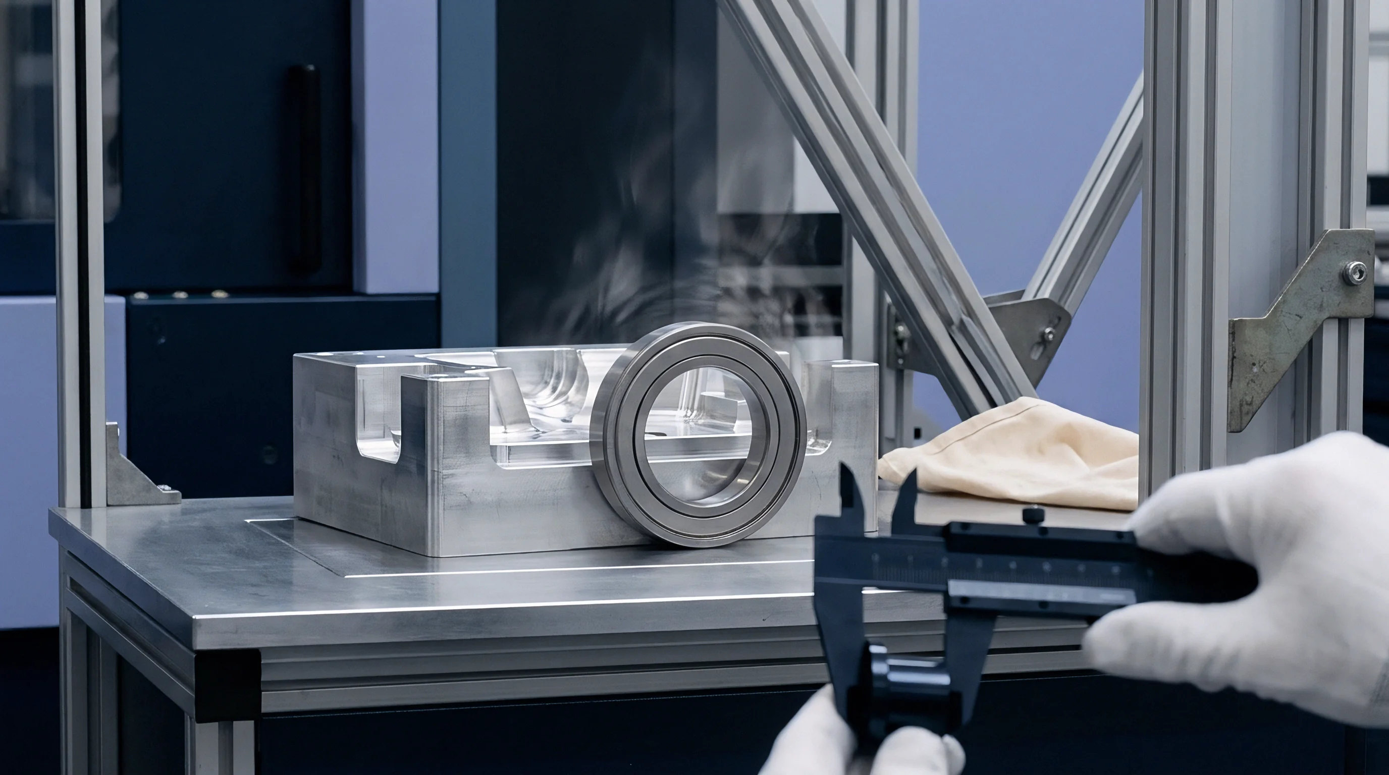
Volumetric Contraction Math for Precision Resins
Cavity sizing formulas must balance polymer volumetric contraction against steel thermal expansion at operating temperature. Standard linear cavity sizing scales nominal part dimensions by the sum of unity, the polymer shrinkage factor, and the steel’s thermal expansion offset. Material supplier shrinkage data, however, reflects flat ASTM test bars molded under laboratory conditions; production parts experience constrained shrinkage from rib configurations, wall transitions, and core pin geometry.
Relying exclusively on nominal resin shrinkage data leads to undersized internal features and oversized perimeter cavities. Core pins mechanically restrict internal resin contraction, forcing the cooling polymer to bind around the steel, while external walls contract freely away from the tooling. Cavity dimensions that fail to account for localized mechanical constraint cause binding and fit issues during final assembly.
- Anisotropic Shrinkage Vectoring aligns cavity offsets along mold flow lines, accounting for high longitudinal contraction parallel to melt velocity and reduced transverse contraction across flow channels.
- Thermal Expansion Differential adjusts cavity block sizing for operational temperatures, balancing core steel expansion at 80 degrees Celsius against polymer solidification shrinkage.
- Hydrostatic Pack Pressure Compensation scales cavity volume down by 0.05 percent per 10 Megapascals of holding pressure applied during the polymer packing phase.
- Crystallite Phase Volumetric Step calculates the volumetric drop occurring during semi-crystalline resin phase changes during mold cooling cycles.
Overlooking grain orientation and isotropic stability when picking steel grades produces out-of-spec cavities that require secondary EDM passes, replacement core pins, or complete mold base remachining after qualification failures.

Distortion
Heat treatment converts soft annealed tool steel into a hardened martensitic matrix built for high-volume cycling. This phase change alters the volumetric density of the block: martensite has a larger specific volume than annealed ferrite and carbide structures. Depending on carbon and alloy content, quenching generates an internal volume expansion of 0.5 percent to 1.2 percent, which distorts asymmetric cavity geometry if left unmanaged.
Variable wall sections exacerbate residual stress during heat treatment. Thin sections quench and transform to martensite rapidly, expanding while heavier adjacent sections remain hot and ductile. As the heavier sections catch up, cool, and expand, complex internal stress fields develop.
If stress-relief tempering is rushed or inadequate, these residual stresses release during finish wire EDM or high-speed milling, pulling cavity walls inward or twisting features off centerline.
Thermal Processing Profiles for Tool Steels
Vacuum heat-treatment protocols dictate final dimensional accuracy. High-alloy hot-work steels like AISI H13 (1.2344) and stainless grades like AISI S136 (1.2083) require staged preheating before reaching austenitizing temperatures. Rapid heating sets up thermal gradients across features, driving distortion before phase transformation even begins.
Preheating plateaus at 550 degrees Celsius and 850 degrees Celsius equalize surface and core temperatures before the final ramp to 1020 degrees Celsius.
Nitrogen gas quenching pressure controls the cooling rate through the critical transformation range. Inadequate pressure leaves untransformed austenite in the microstructure, which later converts to untempered martensite at ambient operating temperatures, causing cavities to grow dimensionally over months of production.
| Steel Grade | Austenitizing Temp (°C) | Quench Medium / Pressure | Tempering Regime | Retained Austenite % | Post-Heat Volumetric Drift (mm/mm) |
|---|---|---|---|---|---|
| AISI H13 (1.2344) | 1020 – 1040 | N2 Gas at 6 Bar | Triple Temper at 560°C | < 2.0% | +0.0008 to +0.0012 |
| AISI S136 (1.2083) | 1010 – 1030 | N2 Gas at 5 Bar | Double Temper + Cryo | < 1.0% | +0.0004 to +0.0007 |
| AISI P20+Ni (1.2738) | Pre-hardened (860°C) | Oil Quenched (Mill) | Factory Tempered | < 0.5% | 0.0000 (As Delivered) |
| AISI S7 (1.2355) | 930 – 950 | Air Cool / Gas 3 Bar | Double Temper at 200°C | < 3.5% | +0.0015 to +0.0022 |
| NAK80 (Pre-hard) | Pre-hardened (520°C) | Age Hardened | Precipitation Aged | < 0.1% | 0.0000 (As Delivered) |

Cryogenic Stabilization and Residual Stress Relief
Sub-zero cryogenic processing between tempering cycles converts retained austenite into stable martensite. Dropping the block temperature to minus 180 degrees Celsius with liquid nitrogen vapor destabilizes the austenite and forces the transformation to finish. Subsequent tempering relieves the stresses introduced during this cryogenic step.
Skipping this stage on optical molds or connector cavities invites dimensional drift that easily breaches five-micron tolerances under high-volume production.
GB/T 1299 class 4 carbide segregation limits cause uncontrolled dimensional drift during vacuum quenching, voiding dimensional guarantees under standard supply agreements.
Thermal stress relief prior to final finishing isolates parts from sudden movement. Heavy roughing clears substantial metal and upsets the block’s internal mechanical equilibrium. Soaking the rough-machined block at 600 degrees Celsius for two hours per 25 millimeters of thickness relieves these machining stresses, ensuring features hold true position during subsequent finish grinding or wire EDM.
- Rough machine cavity block leaving 1.5 millimeter stock allowance on all functional surfaces to account for thermal relaxation.
- Execute thermal stress relief at 600 degrees Celsius with slow furnace cooling down to 200 degrees Celsius to clear residual machining stress.
- Semi-finish machine functional geometry leaving 0.3 millimeter stock allowance for final grinding and electrical discharge operations.
- Perform vacuum heat treatment including dual preheat steps, high-pressure nitrogen gas quenching, and sub-zero cryogenic soak.
- Execute triple tempering cycles at specific alloy secondary hardening peaks to minimize retained austenite levels below one percent.
- Wire EDM core profiles and high-speed CNC finish grinding under temperature-controlled workshop conditions.
Cavity Dimensional Budgeting across Size Classes
Allocating tolerance budgets requires distributing allowable part variation across heat-treat drift, CNC positioning tolerances, and polymer shrinkage spread. Distortion scales non-linearly with block mass: inserts under 50 millimeters expand predictably, but core blocks over 300 millimeters develop steep thermal gradients between the outer skin and interior during quenching, resulting in saddle-shaped warpage across ground mounting faces.
Bowing across mold base seating planes often leads fitting crews to hand-grind the backs of blocks, compromising perpendicularity relative to core pin bores. Uneven seating under clamping tonnage bends core pins off-axis, producing parting-line flash. Budgeting for size-dependent distortion prevents these manual corrections during final assembly.
Cavity dimension discrepancies are frequently attributed to resin shrinkage variance or melt flow inconsistencies from raw material suppliers, deflecting attention from uncalibrated furnace cycles or omitted stress-relief steps during core machining.


Chemistry
Alloy composition dictates hardenability, corrosion resistance, thermal conductivity, and microstructural consistency. When drawings specifying AISI or DIN grades transfer to offshore tool shops, material substitutions often occur. Domestic grades sharing nominal designations frequently carry broader impurity allowances.
Minor deviations in carbon, chromium, or sulfur content shift phase transformation temperatures, altering post-quench hardness and cavity shrinkage behavior.
Substituting domestic 4Cr13 for AISI S136 (1.2083) shifts the carbon-to-chromium ratio. Lower chromium weakens resistance to acidic off-gassing from flame-retardant resins, while excess carbon produces coarse primary chromium carbides that pull out during diamond polishing, pitting cosmetic cavity faces. Polishing out these pits enlarges the cavity and can push critical dimensions out of tolerance.
Spectral Analysis of Alloy Steel Compositions
Confirming core steel chemistry requires optical emission spectrometry or laboratory X-ray fluorescence, as mill certificates from intermediate steel traders may not match delivered stock. Chemistry must stay strictly within specification bands: manganese and silicon deoxidize the melt but broaden austenite stability, chromium provides through-hardenability, and vanadium forms fine carbides that resist coarsening at high austenitizing temperatures.
Comparing core steel mill certificates directly against dimensional inspection records frequently exposes gaps between specified alloys and delivered metal. In hot-work steels like H13 (1.2344), molybdenum prevents temper embrittlement; under-alloyed, low-molybdenum substitutes sacrifice heat resistance, accelerating thermal fatigue and micro-crazing at rib roots under cyclic molding temperatures.
| Element (Weight %) | AISI H13 (1.2344) Standard | GB/T 1299 4Cr5MoSiV1 | AISI S136 (1.2083) Standard | GB/T 1299 4Cr13 Premium | Impurity Tolerance Limit |
|---|---|---|---|---|---|
| Carbon (C) | 0.37 to 0.42 | 0.32 to 0.45 | 0.36 to 0.45 | 0.38 to 0.45 | +/- 0.01 |
| Chromium (Cr) | 4.75 to 5.50 | 4.75 to 5.50 | 12.0 to 14.0 | 12.0 to 14.0 | +/- 0.15 |
| Molybdenum (Mo) | 1.10 to 1.75 | 1.10 to 1.75 | 0.40 to 0.80 | — (Omitted) | +/- 0.05 |
| Vanadium (V) | 0.80 to 1.20 | 0.80 to 1.20 | 0.25 to 0.40 | — (Omitted) | +/- 0.03 |
| Silicon (Si) | 0.80 to 1.20 | 0.80 to 1.20 | < 1.00 | < 0.80 | +/- 0.05 |
| Phosphorus and Sulfur impurities must remain below 0.015 weight percent to ensure polishability and prevent micro-cracking during vacuum heat treatment. | |||||
Material Substitution Tactics in Mould Fabrication
Toolmakers often leverage subtle discrepancies between international steel standards during procurement. Standard GB 3Cr2Mo matches nominal AISI P20 composition but omits the nickel additions found in DIN 1.2738. Without nickel, through-hardenability drops in blocks over 200 millimeters thick: the center of deep cavities cut into standard P20 can drop to 24 HRC while surface faces measure 30 HRC.
These soft core centers yield under injection pressures, leaving permanent depressions in deep features.
Elevating sulfur is another common cost-saving measure. Free-machining grades like AISI P20+S (1.2312) carry up to 0.10 percent sulfur to speed up cutting and break chips via manganese sulfide inclusions. These same inclusions prevent high-gloss diamond polishing and ruin chemical or laser surface texturing.
When molding corrosive resins like PVC or fluoropolymers, the higher sulfur content leads to surface pitting within weeks of commissioning.
Pre-hardened core steel purchased without mill test reports from verified state-owned foundries shifts the dimensional risk entirely onto the buyer during high-volume molding runs.
Verifying steel origin requires direct spectral testing of delivered raw blocks before roughing starts. Independent labs check trace chemistry to ensure sulfur, phosphorus, and dissolved oxygen remain within the micro-cleanliness thresholds needed for high-polish tooling.
- X-Ray Fluorescence Spectrometry provides rapid non-destructive surface chemistry screening of incoming raw tool blocks prior to machine shop intake.
- Optical Emission Spectroscopy evaluates light elements including carbon, nitrogen, and trace impurities from destructive millings extracted from block edges.
- Micro-Cleanliness Rating per ISO 4967 quantifies non-metallic sulfide, alumina, silicate, and globular oxide inclusion density across polished core samples.
- Cross-Sectional Hardness Profiling validates hardenability depth across heavy core sections, ensuring core-to-surface micro-hardness variance stays under two HRC points.
Hardness Profiles and Cavity Degradation Mechanics
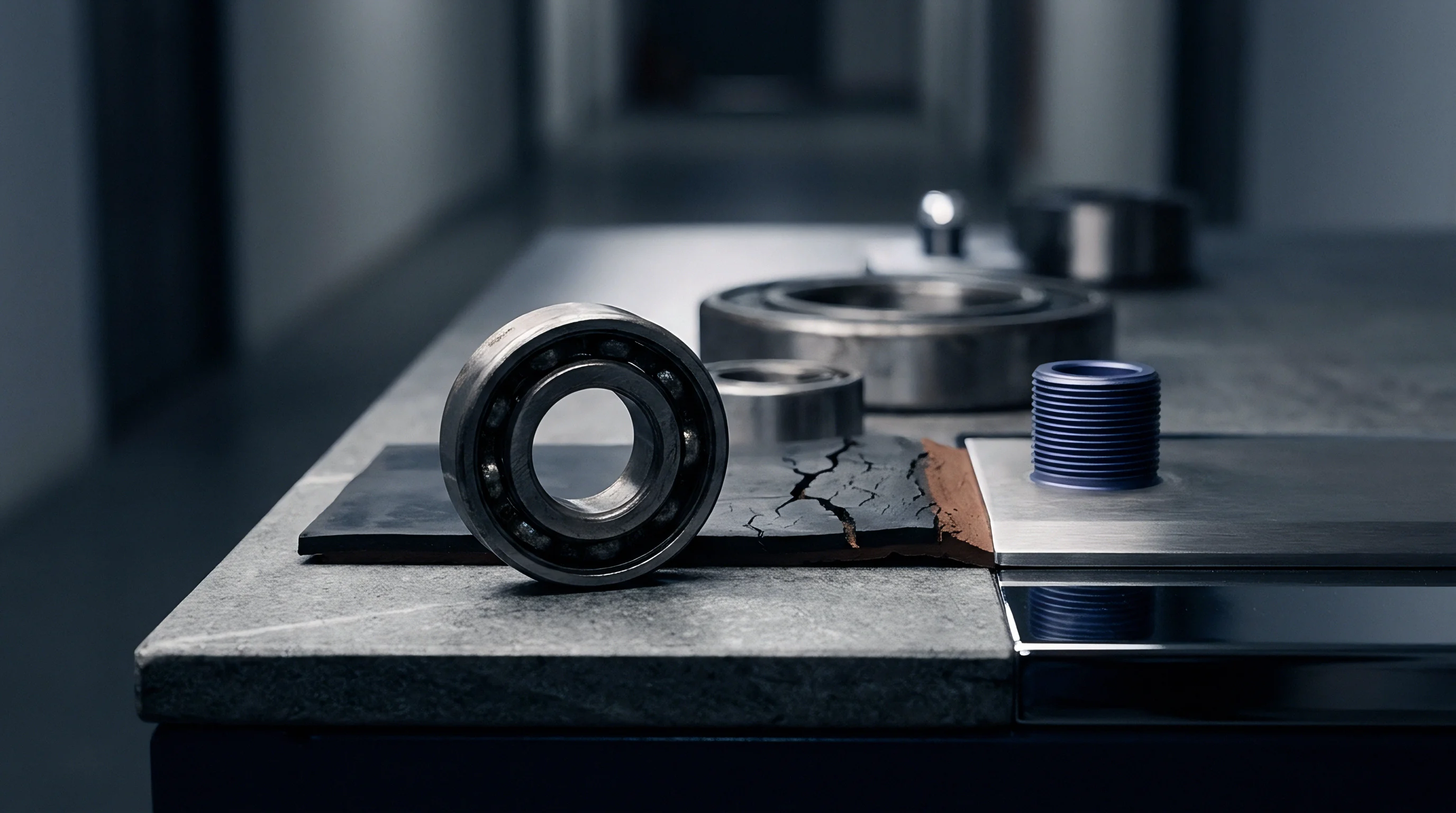
Operating hardness determines how well cavities resist cyclic clamping forces and resin erosion. Steel tempered below specification deforms under 500 to 2000 metric tons of clamp tonnage. Over thousands of shots, shut-off lands collapse by several micrometers, increasing cavity depth and opening flash gaps at parting lines ~ forcing continuous process adjustments that distort planned shrinkage allowances.
Surface treatments like gas nitriding or TiN physical vapor deposition deposit thin, hard outer layers on core pins and slides, reaching 65 HRC up to 0.15 millimeters deep to resist abrasive glass-filled resins. If the underlying core steel lacks sufficient yield strength, however, the hard shell flexes under injection pressure and spalls like an eggshell. This flaking exposes the softer substrate and accelerates wear along critical sealing surfaces.
The tooling agreement stipulates that raw core steel blocks undergo certified spectral analysis by an accredited third-party laboratory prior to machining, and any block failing to match specified alloying element limits shall be rejected at the toolmaker’s sole expense without schedule adjustments.


Audit
Verifying cavity dimensions requires coordinate measuring machine routines run in temperature-controlled rooms. Measuring steel blocks outside standard 20 degrees Celsius calibration targets introduces thermal expansion errors: a 500 millimeter block expands by 6.0 micrometers for every degree Celsius above calibration temperature. Inspecting warm blocks straight off the mill produces false dimensional passes, hiding out-of-tolerance conditions until final assembly.
Measuring complex core surfaces requires alignment against native CAD datums through structured alignment routines. Referencing off raw, cast mold edges introduces cosine measurement errors across angled features. Locating precision ground datum spheres or reference bushings directly on core inserts provides consistent alignment across shop-floor machine datums and final quality dossiers.

Coordinate Measuring Machine Inspection Profiles
Tactile probe routines must account for stylus deflection and tip offsets when probing deep pockets, as thin styli flex under contact loads in high-aspect rib slots and distort measured values. Non-contact 3D blue-light scanning captures high-density surface point clouds across freeform geometry, revealing volumetric distortion that single-point touch probes bypass.
Scanning core inserts before and after initial trials separates elastic deflection under injection pressure from permanent plastic deformation. High cavity pressures push unsupported sidewalls outward during injection. If supporting pillars are undersized or missing, cavity walls can deflect 0.05 to 0.15 millimeters during packing, creating thick-walled parts that incorrectly read as undersized polymer shrinkage during quality checks.

How Does Cavity Wear Alter Measured Shrinkage over Tool Life?
Cavity wear continuously shifts effective tooling dimensions over long production runs. Abrasive fillers like calcium carbonate and glass beads scour cavity surfaces, gradually opening up wall dimensions, while acidic degradation products from PVC processing etch steel boundaries and round off shut-off corners. This progressive cavity expansion increases molded part sizes, masking the underlying resin shrinkage.
Cavity dimensions verified at ambient factory temperatures expand beyond allowable tolerances when oil heater channels bring the mold block to operating equilibrium.
Accommodating this wear requires steel-safe tolerance budgeting during initial design. Sinking cavities toward the lower material condition limit allows abrasive wear to drift dimensions toward nominal center over the first 250,000 shots. Conversely, machining core pins to upper material limits lets pin wear work toward nominal without breaching minimum material specs early in tool life.

Statistical Process Control for Tooling Validation
Evaluating multi-cavity tooling relies on process capability indexes (Cpk) calculated across trial shots. Wide dimensional scatter from cavity to cavity usually indicates uneven water flow or imbalanced hot runner nozzle temperatures rather than metallurgical variation. These thermal differentials alter localized steel expansion and resin cooling rates, invalidating calculated shrinkage offsets.
Imbalanced filling over-packs gates near the runner while starving distant cavities. Over-packed cavities show reduced volumetric shrinkage due to higher melt density, while under-packed cavities shrink heavily and develop sink marks. Achieving uniform part dimensions across all positions requires balancing hot runner pressure drops and regulating flow rates across individual cooling circuits with automated flow-meters.
- Initial Sample Inspection Report Validation compares 3D scan point clouds against design CAD files across all individual mold cavities to establish statistical Cpk capability baseline figures.
- Thermal Equilibrium Mapping records cavity block temperature distributions using calibrated infrared cameras to verify uniform core heating before running dimensional sampling trials.
- Volumetric Filling Balance Audit evaluates short-shot injection samples at 20 percent, 50 percent, and 90 percent filling steps to verify synchronized melt front progression across multi-cavity layouts.
- Dynamic Deflection Sensor Tracking measures transient core pin displacement during the high-pressure packing phase using cavity-mounted inductive displacement transducers.
Can multi-cavity steel allocations maintain five-micron tolerance bands across diverse core suppliers without mandatory standardized heat treatment and CMM inspection protocols?


Transfer
Moving injection molds between production facilities exposes gaps in tooling ownership and cavity IP documentation. Buyers funding tool construction often assume invoice payment automatically confers legal title to cores and cavities under foreign jurisdictions. In China, however, legal frameworks treat physical possession as prima facie evidence of operational control, complicating mold recovery if title perfection was omitted during initial NNN contract drafting.
Securing title requires bilingual tooling development agreements specifying that ownership of cores, cavity inserts, EDM electrodes, and custom core-pull mechanisms transfers immediately upon down payment. Contracts should tie each tool to permanent, stamped asset tracking numbers linked directly to asset registers, commercial invoices, and bills of lading.

Legal Perfection of Tooling Ownership in China
Protecting cavity IP requires filing local design patents in China before sharing 3D CAD files with mold shops. Transferring proprietary CAD geometry without local filings leaves rights-holders vulnerable to unauthorized mold duplication. Foreign patents do not prevent a domestic toolmaker from using production CAD files to cut duplicate core sets for local competitors unless Chinese design patents or utility model registrations are already in place.
Registering mold marks and cavity patents with China Customs creates an enforcement channel against unauthorized tool exports and counterfeit shipments. Recordation gives border authorities the mandate to detain tooling attempting transit under altered asset plates or false paperwork, blocking the export of proprietary steel assemblies.
Customs Clearance and Tooling Expatriation Mechanics
Exporting mold cores and assemblies across borders involves thorough customs audits that compare declared asset valuations against physical condition and production history. Declaring production molds at scrap steel value to reduce import tariffs routinely triggers audits, seizures, and administrative penalties for customs fraud. Secondary fitting and qualification costs average 18 percent of initial mold capitalization during facility transfers.
Export documentation must include a complete material provenance file detailing steel origins, heat-treat records, and official tax invoices (fapiao) for original fabrication labor. Lacking valid fapiao blocks formal export declarations, leaving buyers liable for retroactive value-added taxes and local surcharges before customs grants clearance.
Contractual Remedies for Mold Detention and IP Extraction
Handling mold detention during supplier terminations requires clear contractual mechanisms. Toolmakers facing contract cancellation routinely place statutory commercial liens over core and cavity blocks, citing disputed engineering change fees, maintenance costs, or raw material price increases. These liens legally halt tool removal pending court resolution, freezing production for months.
Agreements should include an explicit waiver of statutory liens, governed under Chinese law with jurisdiction assigned to designated PRC courts. Specifying offshore arbitration venues like London or Singapore delays emergency relief, as Chinese courts do not enforce foreign emergency arbitral asset preservation orders against local suppliers in physical possession of tooling. Naming the specialized IP court or district court local to the supplier’s facility provides a direct path to asset preservation orders and court-enforced mold retrieval.
Tooling title perfection requires physically stamping bilingual asset ownership plates onto the mold base, executing registered title transfer agreements under Chinese law prior to tool build, and retaining native CAD files in escrow to guarantee immediate supply chain independence when relocating molds across international borders.