Quantifying Financial Liability for Latent Intermetallic Joint Failure in High-Humidity Offshore PCB Assembly
Quantifying offshore PCB joint liability requires linking ionic contamination data to Peck acceleration models and contractual latent defect terms.

Swell
Relative humidity levels exceeding 75 percent in marine assembly facilities force water vapor into porous epoxy laminate matrices at rates governed by Fickian diffusion. Printed circuit board assemblies stored or processed in coastal manufacturing hubs across Guangdong and Zhejiang absorb ambient water vapor quickly when environmental control systems drop below specification. Moisture molecules occupy micro-voids within the FR-4 glass-epoxy matrix, increasing the internal mass and inducing localized volumetric expansion.
This volumetric shifting exerts continuous z-axis strain on plated through-holes and surface-mount land patterns before the reflow cycle begins.
Thermal activation during reflow converts entrapped liquid water into pressurized steam. Peak temperatures reaching 245 degrees Celsius generate internal vapor pressures above 3.0 megapascals within encapsulated voids. Steam expansion forces microscopic delamination at the interface between the copper foil and the resin substrate.
Solder joint formation over damp pads leads to vapor venting through the molten alloy. This venting leaves behind gross blowholes, pinhole micro-voids, and incomplete metallic wetting along the pad boundary. The resulting mechanical weak points concentrate thermal fatigue stresses once the assembly enters offshore service.
Ambient storage at 85 percent relative humidity increases FR-4 laminate water retention by 0.35 percent by weight within 48 hours, triggering internal steam pressures above 3.0 megapascals during reflow.
Hygroscopic Diffusion Mechanisms in Glass Reinforced Substrates
Substrate moisture absorption obeys classic thermodynamic laws. Permeation rates depend on ambient vapor pressure, ambient temperature, and the specific resin composition of the laminate. High-density interconnect designs with thin dielectrics suffer rapid saturation.
The water molecules bound to polymer chains reduce the glass transition temperature of the resin matrix. A lower glass transition temperature lowers the mechanical stiffness of the board at elevated processing temperatures. Z-axis expansion rates rise sharply once the assembly passes through its glass transition point, straining mechanical interfaces.
Uncontrolled pre-bake storage cycles compound substrate degradation. When copper pads experience hygroscopic expanding forces, the spatial alignment of fine-pitch components shifts off target during component placement. Solder paste deposits undergo slump under high humidity.
Slumping paste bridges adjacent pads, altering the volumetric ratio of flux vehicle to metallic alloy across the joint array. Reduced alloy volume per joint lowers total mechanical strength and alters intermetallic growth geometry.

Moisture Sensitivity Level Compliance and Outgassing Mechanics
Component handling protocols defined by IPC/JEDEC J-STD-020E govern the allowable floor life of moisture-sensitive devices. Operators who exceed maximum exposure limits risk interior plastic package cracking and bond-wire lift during thermal processing. Outgassing moisture during the liquid phase of solder reflow disrupts the chemical action of fluxing agents.
Volatilized water reduces the capability of rosin acids to strip native oxides from copper surface finishes. Solder alloys fail to achieve full spreading, leaving un-reacted copper regions along the joint perimeter. Contract manufacturers frequently claim that unconditioned factory floor exposure remains within ambient margins during summer monsoons, attributing latent moisture entrapment to transit container condensation.

Phase
Intermetallic compound formation begins immediately when molten tin-based solder dissolves underlying copper substrate metal. Dissolution produces a boundary layer consisting of two distinct intermetallic structures: eta-phase copper-tin alloy (Cu6Sn5) adjacent to the solder bulk, and epsilon-phase copper-tin alloy (Cu3Sn) adjoining the copper pad. The initial growth provides the necessary chemical bond between solder and printed circuit board surface finish.
Continued exposure to thermal energy and electric bias drives solid-state diffusion, causing the intermetallic layer to thicken throughout the operational lifespan of the electronics.
Offshore marine environments subject solder joints to elevated temperature baselines and non-stop humidity. High humidity accelerates galvanic corrosion and stress-assisted diffusion at the intermetallic boundary. As tin atoms diffuse faster into the copper matrix than copper atoms diffuse into the solder, microscopic vacancies coalesce into Kirkendall voids along the Cu3Sn interface.
Kirkendall voiding destroys interfacial cohesion, transforming a ductile solder connection into a brittle structural failure point susceptible to micro-cleavage under operational mechanical shock.
| Phase Structure | Chemical Formula | Crystal System | Hardness (HV) | Growth Energy (eV) | Primary Failure Mode |
|---|---|---|---|---|---|
| Eta Intermetallic | Cu6Sn5 | Monoclinic / Hexagonal | 370 – 410 | 0.78 | Ductile fatigue cracking |
| Epsilon Intermetallic | Cu3Sn | Orthorhombic | 340 – 380 | 0.95 | Brittle Kirkendall voiding |
| Nickel Intermetallic | Ni3Sn4 | Monoclinic | 520 – 600 | 1.12 | Interfacial spallation |
| Silver Intermetallic | Ag3Sn | Orthorhombic | 160 – 220 | 0.45 | Matrix void nucleation |
Intermetallic Microstructure Dynamics and Void Formation
Metallurgical evolution proceeds through specific chemical transformations. Lead-free alloys such as SAC305 (Sn3.0Ag0.5Cu) generate distinct intermetallic morphologies compared to legacy tin-lead compositions. High tin content drives intense copper consumption from the substrate pad during reflow.
Elevated temperatures sustained over extended periods promote the excessive growth of Cu6Sn5 needles into the bulk solder matrix. These elongated intermetallic structures increase localized brittleness and act as internal stress concentrators under cyclic loading.
Excessive intermetallic thickness degrades mechanical compliance. Thin intermetallic layers below 1.5 micrometers preserve joint elasticity. Layers expanding beyond 4.0 micrometers accumulate high micro-strain.
Under high humidity, moisture penetration down micro-cracks accelerates localized oxidation of the epsilon phase layer, forming non-conductive copper oxide films that trigger intermittent open circuits.
Thicker intermetallic layers shift failure behavior from ductile bulk solder shear to brittle interfacial fracture under shock loads.

Metallurgical Transformations under Continuous Thermal Stress
Solid-state intermetallic growth continues long after assembly line inspection. Heat generated by high-power offshore compute nodes drives copper-tin diffusion continuously. Lead-free formulations containing nickel micro-alloying additions slow down Cu3Sn layer growth by forming stable (Cu,Ni)6Sn5 barrier structures.
Failure to control alloy purity allows trace contaminants to disrupt this protective effect.
- Interfacial Void Coalescence occurs when vacancy diffusion rates exceed lattice restructuring capacities, generating continuous structural micro-planes along the copper substrate boundary.
- Phase Inversion Breakdown occurs when high temperatures convert hexagonal Cu6Sn5 structures into monoclinic crystal configurations, introducing internal shear strain across the joint.
- Galvanic Anode Dissolution occurs when moisture films connect phase boundaries of differing electrochemical potential, dissolving tin-rich regions surrounding intermetallic crystals.
- Dendritic Whisker Growth occurs when compressive mechanical stresses drive tin ion migration across microscopic surface imperfections, forming conductive paths across fine-pitch leads.
Quantifying joint reliability requires tracking these microstructural phase changes over multi-year deployment cycles. The precise volumetric threshold at which planar Kirkendall void arrays transform into active mechanical failure lines under cyclic sea-state micro-vibration remains unresolved.


Stress
Offshore electronics installations experience continuous environmental and mechanical forcing functions. Atmospheric conditions on marine platforms deliver relative humidity levels above 85 percent combined with airborne sodium chloride concentrations exceeding 0.05 milligrams per cubic meter. Temperature swings driven by operational loading cycles generate cyclic thermal strain across component packages, printed circuit board substrates, and solder joint arrays.
Thermal expansion mismatch between ceramic component bodies and FR-4 laminates induces mechanical shear within intermetallic boundary layers.
Accelerated life testing quantifies latent field risk by compressing years of operational exposure into weeks of chamber testing. Peck’s acceleration model correlates ambient relative humidity and temperature to failure timelines, mapping humidity acceleration through an empirical power-law exponent. Combining Peck’s relationship with Arrhenius thermal kinetics yields an equation capable of predicting time-to-failure for intermetallic joints under extreme marine exposure.
| Temperature (C) | Relative Humidity (%) | Acceleration Factor | Equivalent Hours | Predicted Micro-Strain |
|---|---|---|---|---|
| 45 | 60 | 1.0 | 10,000 | 0.0012 |
| 60 | 75 | 4.8 | 2,083 | 0.0035 |
| 75 | 85 | 18.3 | 546 | 0.0089 |
| 85 | 85 | 37.6 | 265 | 0.0154 |
Peck Acceleration Calculations for High Humidity Offshore Profiles
Peck’s acceleration factor formula combines thermal activation energy with ambient humidity exponent values. Formula calculations use an activation energy of 0.90 electron-volts for intermetallic corrosion mechanisms and a humidity exponent factor of 2.6 for moisture condensation dynamics. Operating environment baselines of 30 degrees Celsius and 50 percent relative humidity provide the control reference.
Exposing test samples to 85 degrees Celsius and 85 percent relative humidity inside controlled stress chambers yields an acceleration factor of 37.6 times baseline degradation rates.
Engineers use this mathematical relationship to schedule stress testing. Testing assemblies for 265 hours under 85/85 accelerated conditions reproduces the thermal and hygroscopic aging experienced during 10,000 operational hours in typical marine environments. Solder joints exhibiting compromised intermetallic integrity fail during accelerated exposure, surfacing micro-cracks before hardware units ship to offshore installations.
Vibrational Shear and Fracture Propagation
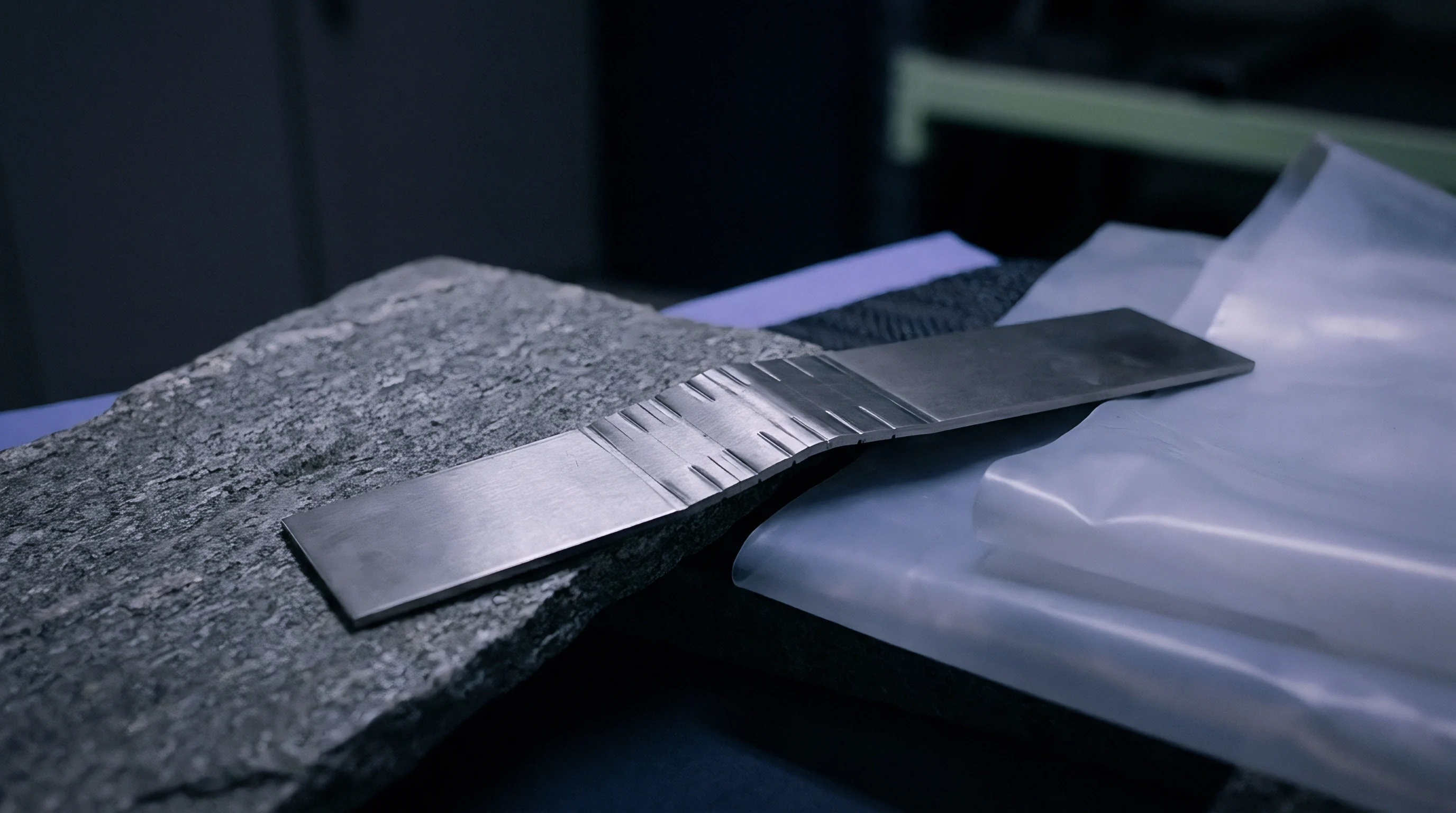
Offshore structures subject control electronics to low-frequency structural vibration and high-frequency wave-impact shock. Continuous vibration forces cyclic micro-bending across printed circuit board assemblies. Solder joints located near board mounting points endure peak flexural shear stresses.
Brittle intermetallic phases cannot deform plastically to accommodate this cyclic flexure, causing micro-fractures to initiate along the Cu3Sn interface.
Micro-cracks act as capillary channels for entrapped moisture films containing dissolved ionic flux residues. Hydrostatic pressure generated during cyclic thermal expansion drives liquid deeper into the joint core. The combination of cyclic mechanical shear and localized electrochemical corrosion accelerates crack growth rates by orders of magnitude compared to dry environmental conditions.
Solder joints lose cross-sectional load area until complete electrical open circuits occur. Thicker IMC structures predictably shift joint failure modes from gradual strain accommodation to catastrophic brittle interfacial shear under sudden impact.

Audit
Preventing latent intermetallic failures requires direct physical verification at the assembly factory floor. Relying on end-of-line functional electrical testing fails to detect initial micro-voiding or unreacted flux residues trapped beneath low-profile component packages. Verification operations require rigorous environmental control monitoring, SMT reflow profile optimization, and destructive metallurgical analysis on representative production samples.
Technical teams audit the operating environment continuously. Relative humidity inside SMT line enclosures must remain below 60 percent to prevent raw printed circuit boards and opened solder paste containers from absorbing excess moisture. Automated environmental logging systems record humidity and temperature levels at fifteen-minute intervals.
Deviation beyond specified bands holds affected production batches for mandatory bake-out processing under controlled thermal profiles.
Where Do Flux Residues Convert Intermetallic Growth into Latent Failure?
Flux vehicles designed for lead-free SMT assembly contain organic activators formulated to dissolve surface oxides at elevated temperatures. Incomplete thermal decomposition leaves active acid residues beneath bottom-termination components such as Quad-Flat No-Lead packages. Entrapped activators absorb atmospheric moisture through capillary action, creating localized acidic electrolytes that attack Cu6Sn5 intermetallic structures.
Hydrolysis releases free halide ions, accelerating galvanic dissolution of the solder matrix adjacent to the pad boundary.
IPC-J-STD-001H Requirement 8.1.4 mandates ionic contamination levels below 1.56 micrograms of NaCl equivalent per square centimeter to prevent dendritic creep under bias.
Ion Chromatography and Surface Insulation Resistance Testing
Surface cleanliness evaluation uses analytical techniques specified by IPC-TM-650 test methods. Rose testing provides total bulk ionic counts but lacks the capability to isolate specific corrosive species. Ion chromatography separates and quantifies specific halide species including chloride, bromide, and fluoride ions present on the assembly surface.
- Thermal Reflow Profiling uses calibrating multi-channel thermocouples attached directly to high-mass solder joints to guarantee liquidus dwell times between 60 and 90 seconds.
- Ion Chromatography Profiling extracts surface residues using localized solvent wash mixtures to quantify specific halide concentration levels in micrograms per square centimeter.
- Cross-Sectional Micro-Cleavage polishes metallurgical samples to expose intermetallic boundary layers for direct thickness measurement under scanning electron microscopy.
- Surface Insulation Resistance Analysis applies steady direct-current bias across fine-pitch comb patterns housed inside high-humidity environmental chambers for 168 hours.
Visual inspection standards defined by IPC-A-610H Class 3 establish baseline acceptance criteria for offshore electronics. Solder joints exhibiting dull appearance, irregular wetting angles, or surface micro-fissures require immediate cross-sectional analysis to verify internal intermetallic thickness. Incorporating IPC-A-610H Class 3 latent defect definitions into purchase agreements shifts the burden of proof for ionic cleanliness directly to the fabricator.


Calculus
Quantifying financial liability for latent solder joint failures requires converting physical degradation models into financial risk distributions. Intermetallic failure rates follow two-parameter Weibull statistical distributions characterized by shape parameter beta and scale parameter eta. Early wear-out failures caused by brittle intermetallic cracking produce Weibull shape parameters between 2.2 and 3.5.
These values indicate accelerating failure probability as operating hours accumulate in high-humidity marine environments.
Total financial liability extends far beyond the direct unit manufacturing cost of the printed circuit board assembly. Offshore deployments incur substantial logistics and demobilization expenses. Retrieving failed hardware from offshore platforms requires specialized service vessels, certified offshore labor crews, and planned operational downtime for critical platform infrastructure.
Financial risk models must sum direct component replacement costs, field retrieval logistics, vessel charter fees, and contractual delay penalties.
Financial Risk Exposure Allocation Matrix
Commercial exposure calculation incorporates tiered liability categories mapped against measured defect rates within shipped production lots. The table below delineates financial exposure allocation across a standard manufacturing run of 10,000 sub-sea control modules.
| Defect Severity Category | Latent Failure Probability | Primary Cost Driver | Offshore Direct Expense | Supplier Allocable Liability |
|---|---|---|---|---|
| Minor Intermetallic Degradation | 0.5% – 1.5% | Onsite Module Swapout | $2,500 per unit | 100% Component Replacement |
| Moderate Interfacial Voiding | 1.5% – 5.0% | Vessel Demobilization | $45,000 per vessel-day | 80% Direct Logistics Expense |
| Severe Brittle Cleavage Array | > 5.0% | Complete Field Recall | $1,200,000 total event | 100% Capped Contract Limit |

Worked Financial Exposure Scenario for Offshore Deployments
Consider an offshore wind farm deployment utilizing 5,000 power control assemblies manufactured in a high-humidity coastal facility. Assume an undetected reflow profile deviation caused excessive Cu3Sn intermetallic growth and Kirkendall voiding across 4.0 percent of the production lot. Over a three-year initial operating window under marine humidity, Weibull models project that 80 percent of the affected population will fail in service, resulting in 160 active field failures.
- Calculate direct hardware replacement expenses by multiplying 160 failed units by the single-unit manufactured assembly price of $850, yielding $136,000 in direct material expense.
- Calculate offshore retrieval logistics costs by multiplying 16 field intervention trips by the daily offshore support vessel charter rate of $35,000 per day, totaling $560,000 in charter fees.
- Calculate certified offshore engineering labor fees by allocating 320 specialized technician hours at $275 per hour, adding $88,000 in technical labor costs.
- Calculate operational downtime penalties for power generation disruption at $5,000 per unit failure event, resulting in $800,000 in contractual liquidated damages.
- Sum the sub-totals to arrive at a total field financial liability exposure of $1,584,000 for the single assembly batch defect event.
Contractual liability caps often limit supplier warranty exposure to 100 percent of total purchase order value unless contracts explicitly include gross negligence or latent defect carve-out clauses. When purchase orders for the 5,000 assemblies total $4,250,000, unhedged financial liability absorbed by the system integrator equals $1,584,000 if supplier agreements lack latent defect indemnification provisions. Inadequate financial exposure modeling leads to catastrophic unhedged warranty reserves during mass offshore field retrievals.


Clause
Legal recourse for latent solder joint failures depends heavily on contract structure and applicable governing law. Standard express warranties typically expire twelve to twenty-four months after delivery. Latent intermetallic degradation often manifests between month eighteen and month thirty-six of offshore field service, after standard warranty windows close.
Buyers must negotiate specific legal definitions that categorize microscopic intermetallic degradation and moisture-induced Kirkendall voiding as hidden manufacturing defects rather than normal operational wear and tear.
Under the People’s Republic of China Civil Code, Article 617 establishes fabricator liability when delivered goods fail to meet specified quality standards. Article 621 governs inspection windows and notice periods for defects. For hidden structural defects that cannot be detected by standard receiving inspection techniques, statutory notice windows extend up to two years from physical delivery unless custom contract terms establish longer survival periods.
Overseas buyers must incorporate clear latent defect survival clauses that override default statutory limitations.

Latent Defect Allocation under PRC Civil Code Frameworks
Drafting enforceable supply contracts requires precise technical definitions linked directly to measurable industry standards. Contracts must explicitly state that failure to comply with IPC-J-STD-001H cleanliness levels or IPC-A-610H Class 3 microsection requirements constitutes a material breach and a latent defect. Language must specify that inspection acceptance at the factory gate does not waive the buyer’s right to pursue indemnification if subsequent laboratory micro-sectioning proves the existence of pre-existing manufacturing flaws.
Contractual Mechanics for Warranty Reserves and Escrow Withholding
Commercial remedies require enforceable financial mechanisms built into supply agreements. System integrators routinely institute a rolling warranty retention fund, withholding 5 to 10 percent of total invoice value for thirty-six months post-delivery. Held funds provide immediate liquidity to cover field recall logistics without initiating cross-border litigation.
Third-party arbitration clauses must specify recognized international arbitration centers located in Hong Kong or Singapore, designating specialized metallurgical experts as technical arbitrators for disputes regarding intermetallic growth mechanics. Escrow retention funds held for eighteen months provide necessary liquidity to offset early field failures without halting active assembly lines.