Establishing Latent Defect Liability Allocation for Interfacial Kirkendall Voiding in Subcontract Microelectronics Assembly
Subcontract packaging agreements require precise metallographic defect thresholds and chemical bath audits to allocate latent Kirkendall failure costs.


Solder
When copper leadframes and substrate bond pads undergo high-temperature storage, atomic interdiffusion across interfacial intermetallic compound layers becomes unbalanced. During reflow and subsequent thermal exposure, tin reacts with copper to form a bilayer structure: eta-phase Cu6Sn5 adjacent to the solder bulk and epsilon-phase Cu3Sn next to the copper substrate. Copper atoms migrate outward into the solder matrix much faster than tin diffuses inward toward the copper base metal.
This asymmetric mass transport creates a net vacancy flux toward the copper interface, where vacancies accumulate at the Cu/Cu3Sn interface or within the Cu3Sn layer itself, coalescing into micro-voids that degrade mechanical integrity and raise electrical resistance over extended operating lifetimes.
Void nucleation begins early. Microstructural examination of aged solder interconnects shows that Kirkendall void density correlates directly with the thickness and growth history of the epsilon-phase Cu3Sn layer. As thermal exposure continues, the Cu3Sn layer thickens by consuming copper from the leadframe.
So long as the copper supply is uninterrupted, the vacancy flux persists. Once vacancy concentration reaches supersaturation, voiding accelerates along crystallographic grain boundaries and interfacial defects. Because this mechanical degradation can proceed without immediate electrical failure, it creates a latent defect that easily evades standard zero-hour functional testing at the assembly plant.

Intermetallic Phase Transformation Dynamics
Metallurgical degradation at the copper-tin boundary stems from unequal diffusion fluxes between copper and tin atoms. The activation energy for copper diffusion through the Cu3Sn layer ranges between 0.8 electron-volts and 1.1 electron-volts, depending on crystal orientation and grain size distribution. Higher operating temperatures accelerate copper vacancy formation exponentially.
Above eighty degrees Celsius, the growth rate of the Cu3Sn phase accelerates, steepening vacancy concentration gradients across the boundary. If the Cu3Sn layer exceeds a threshold thickness of approximately one micron, void coalescence reaches a critical density, allowing continuous micro-cracks to propagate under minimal mechanical shear stress.
This interfacial breakdown occurs during elevated temperature storage testing. When lead-free solder alloys such as tin-silver-copper are reflowed onto direct bonded copper or electroplated copper leadframes, the initial reflow cycle establishes the precursor microstructure. Peak reflow temperatures between two hundred forty and two hundred fifty-five degrees Celsius convert the liquid solder interface into Cu6Sn5 crystals.
Subsequent solid-state thermal aging converts portions of the Cu6Sn5 phase into Cu3Sn. Because the density of Cu3Sn differs from Cu6Sn5, localized volumetric changes induce internal tensile stresses that drive vacancy clustering into planar void networks along the copper boundary.
Solder joint degradation rates double when substrate electroplating organic brighteners decompose into micro-void nucleation sites during thermal storage.

Trace Impurities Accelerating Interfacial Cavitation
Electroplating bath additive residues introduce localized lattice distortions that act as vacancy sinks. Trace elements within the electroplated copper layer ~ specifically phosphorus, sulfur, zinc, and organic brighteners like bis-3-sulfopropyl-disulfide ~ lower the energy barrier for void formation. When electroplating operations run with uncalibrated additive concentrations, co-deposited organic contaminants decompose during high-temperature reflow cycles.
Released gaseous byproduct molecules and residual carbon concentrate at grain boundaries, offering prime nucleation sites for diffusion vacancies.
Subcontract microelectronics assembly plants sourcing low-cost copper substrates from third-party electroplating vendors often introduce variable impurity profiles into production batches. A variation of fifty parts per million of co-deposited sulfur within the electroplated copper layer can increase the Kirkendall void volume fraction by over four hundred percent after isothermal aging at one hundred fifty degrees Celsius for five hundred hours. Consequently, assembly facilities that fail to monitor incoming leadframe chemistry pass latent reliability risks downstream to original equipment manufacturers.
Managing substrate electroplating purity and limiting long-term storage temperatures provides the primary defense against catastrophic interfacial separation.


Screening
Early identification of sub-surface interfacial degradation presents severe metrology challenges during standard quality control. Zero-hour electrical testing and X-ray inspection fail to detect initial micro-void formation because discrete Kirkendall voids neither disrupt electrical continuity nor create the gross volumetric attenuation visible on standard two-dimensional radiographic images. The latent defect remains silent until thermal cycling, mechanical shock, or operational vibration triggers a complete planar fracture across the weakened intermetallic interface.
Quality screening methodologies must combine non-destructive acoustic evaluation with destructive microstructural verification to establish baseline reliability metrics across incoming wafer-level or package-level assembly lots. Standard inline inspection routines rely on sampling strategies that miss batch-level thermal profile anomalies, while relying exclusively on electrical functional pass rates guarantees that latent voiding risks enter final product inventory unrecorded.

Acoustic Microscopy Limits in Zero-Hour Inspection
High-frequency ultrasonic reflection techniques resolve density changes at package interfaces with varying precision. C-mode Scanning Acoustic Microscopy utilizing transducers operating between one hundred megahertz and two hundred thirty megahertz can detect acoustic impedance mismatches caused by interfacial delamination. Resolution limits restrict C-SAM effectiveness when individual Kirkendall voids remain smaller than five hundred nanometers.
At zero-hour inspection, scattered sub-micron voids fail to generate enough acoustic reflection contrast to register as distinct package defects.
Acoustic microscopy becomes effective only after latent voiding progresses into macro-cracks or continuous delamination sheets across the bond pad area. Consequently, C-SAM serves primarily as a post-stress screening tool during qualification reliability testing rather than an inline zero-hour screen. Relying on acoustic screening at final test allows lots with un-coalesced vacancies to pass directly into commercial shipments.

Destructive Metallographic Verification Sequence
Physical cross-sectioning paired with ion beam polishing reveals micro-void coalescence along the gamma-phase intermetallic boundary. Destructive analysis remains the benchmark for measuring Kirkendall void density and Cu3Sn layer thickness. To obtain accurate planar void counts, lab technicians follow a precise preparation protocol designed to avoid smearing soft solder across the brittle intermetallic interface.
- Mount the microelectronic package in low-viscosity epoxy resins cured at temperatures below sixty degrees Celsius to prevent thermal artifact voiding.
- Section the package using a high-precision diamond wafering saw operating at low rotational speeds with synthetic oil coolant.
- Grind the exposed interface using silicon carbide papers down to twelve hundred grit under uniform light mechanical pressure.
- Perform final mechanical polishing using diamond suspensions from three microns down to fifty nanometers on synthetic silk cloths.
- Apply broad ion beam milling using argon gas ions at four kilovolts for fifteen minutes to eliminate mechanical smearing and surface deformation layers.
- Examine the polished Cu/Cu3Sn/Cu6Sn5 interfaces under field-emission scanning electron microscopy at magnifications exceeding ten thousand times.
Destructive physical analysis requires standardized quantification criteria to convert visual micrographs into actionable acceptance decisions. Analysis of the micrograph yields the percentage of total interfacial length occupied by void space; a void area fraction exceeding fifteen percent along the Cu/Cu3Sn interface after environmental stress testing indicates a high risk of early field fatigue failure.
| Technique | Detection Threshold | Sample Prep Time | Cost Per Die | Destructive Status |
|---|---|---|---|---|
| 2D X-Ray Radiography | > 10 microns | Zero (Inline) | $0.05 | Non-Destructive |
| 3D X-Ray Computed Tomography | 1 to 2 microns | 15 minutes | $45.00 | Non-Destructive |
| C-Mode SAM (230 MHz) | 0.5 to 1 micron | 10 minutes | $12.00 | Non-Destructive |
| FIB-SEM Cross-Sectioning | 10 nanometers | 2 to 4 hours | $350.00 | Destructive |
| Broad Ion Beam SEM | 5 nanometers | 1 to 2 hours | $180.00 | Destructive |
J-STD-020 moisture sensitivity classifications fail to isolate sub-surface interfacial voiding when environmental stress testing excludes long-term isothermal aging above one hundred twenty degrees Celsius.
Passing zero-hour electrical testing and standard wire pull tests does not guarantee protection against post-assembly metallurgical aging.


Dossier
Constructing an unassailable technical history requires continuous capture of chemical, thermal, and mechanical variables across the packaging line. When field failures occur eighteen months after deployment, assigning liability hinges on proving whether the subcontract assembler violated agreed process windows or raw material suppliers delivered contaminated components. Without comprehensive lot-level manufacturing dossiers, microelectronics buyers cannot establish proximate cause during commercial dispute arbitration.
The assembly dossier documents every critical variable during substrate fabrication, metallization, storage, and reflow. Because OSAT facilities frequently consider internal bath chemistry logs and real-time reflow sensor data to be proprietary trade secrets, buyers must negotiate explicit data-access covenants in supply agreements to ensure full trace transmission upon request.

Plating Bath Chemistry Audit Records
Electrodeposition monitoring logs capture organic additive consumption rates and impurity buildup. Substrate plating suppliers must run regular chemical analysis using cyclic voltammetric stripping to keep additive concentrations within limit. When organic brightener levels float above nominal specifications, co-deposited organic residue increases by orders of magnitude.
Complete audit records track bath turnover cycles, filter replacements, and atomic absorption spectroscopy scans for trace metal contaminants such as sulfur and zinc.
A complete chemistry dossier pairs batch certification documents from electroplating chemical suppliers with real-time dosing logs from the substrate plating line. If an OSAT fails to produce daily chemical analytical reports for the specific plating run tied to a failed package lot, the legal presumption of process non-conformance shifts onto the assembler.

Reflow Thermal Profile Log Reconciliation
Conveyer speeds and zone temperatures dictate the peak time above liquidus for lead-free interconnects. Reflow profile logs record board-level thermocouple readings across all thermal zones in real time. Excessive reflow temperatures or prolonged liquidus durations accelerate initial Cu6Sn5 growth, thickening the precursor intermetallic layer and leaving high residual stress in the joint.
These logs must also document atmospheric conditions, specifically real-time oxygen concentration inside the nitrogen reflow oven.
- Electroplating Bath Concentration Logs detailing daily cyclic voltammetric stripping analysis for organic brighteners and levelers.
- Substrate Trace Impurity Certificates showing atomic absorption spectroscopy counts for sulfur, phosphorus, and zinc content.
- Reflow Oxygen Sensor Records recording oxygen concentration levels continuously throughout every assembly shift.
- Thermal Profile Calibration Traceability documenting weekly sensor verifications against calibrated external thermocouple standards.
- Raw Material Shelf Life History tracking ambient storage temperature and relative humidity exposure for un-plated leadframes.
Subcontract OSAT facilities operating reflow lines with oxygen contamination exceeding fifty parts per million exhibit a threefold increase in interfacial vacancy accumulation after five hundred thermal cycles.
Incorporating IPC-A-610 Class 3 metallographic sampling schedules into subcontract quality agreements shifts the burden of continuous microstructural compliance directly onto the OSAT.

Indemnity
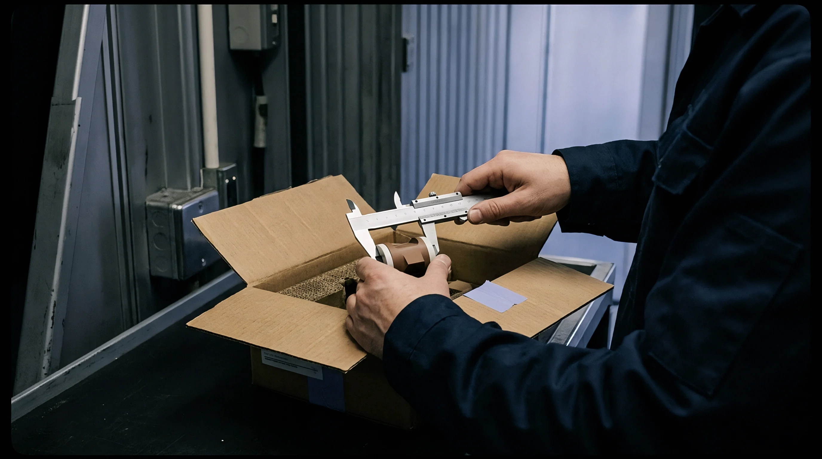
Subcontract assembly agreements frequently fail to allocate commercial risk for structural defects that manifest months after factory acceptance. Standard terms typically provide an express limited warranty covering defects in materials and workmanship for twelve months post-shipment. However, Kirkendall voiding is fundamentally latent ~ void coalescence requires prolonged operational temperatures or extended storage under thermal stress, frequently triggering field failures long after standard warranty periods expire.
Establishing commercial indemnity frameworks requires drafting specific latent defect clauses that override standard limitation-of-liability caps when microstructural evidence proves manufacturing non-conformance. Buyers must negotiate risk allocation structures that separate ordinary workmanship defects from metallurgical non-conformances driven by process parameter drift or material contamination.

Who Bears Warranty Liabilities for Interfacial Cavitation?
Assigning financial responsibility for field failures depends on establishing whether substrate plating defects or reflow parameters triggered vacancy coalescence. Subcontract OSAT contracts often contain broad liability exclusions for customer-supplied materials or specified bill-of-materials components. If the buyer specifies a leadframe supplier whose plating bath chemistry introduced high sulfur content, the OSAT will disclaim assembly liability.
Conversely, if the OSAT sourced the leadframe under a turnkey manufacturing contract, legal responsibility remains with the assembler. Technical root-cause investigations arbitrate these claims by measuring chemical concentration gradients across the interface using energy-dispersive X-ray spectroscopy and secondary ion mass spectrometry. Structuring liability provisions around objective microstructural benchmarks helps resolve multi-tier supplier disputes.

Structuring Latent Defect Discovery Windows
Standard commercial terms limit liability to twelve months from shipment date. For microelectronic packages deployed in mission-critical, automotive, or industrial applications, twelve months is an insufficient window for latent void manifestation. Latent defect covenants extend discovery windows to thirty-six or sixty months specifically for microstructural interfacial separation, though these extended windows usually carry strict conditions regarding storage environments and operational temperatures experienced by the assembly.
Contractual discovery clauses must define exact technical triggers that activate indemnification. A legal definition of latent interfacial voiding should include quantifiable physical metrics, such as a maximum allowable intermetallic void area fraction measured via broad ion beam cross-sectioning. Setting clear quantitative thresholds prevents OSAT counsel from framing thermal aging failures as ordinary operational wear and tear.

Apportionment Rules for Mixed Process Contamination
When substrate suppliers, plating vendors, and OSAT assemblers operate as separate entities, multi-party fault trees establish proportional financial exposure. Joint failure investigations often uncover multiple contributing factors, such as moderate electroplating bath impurities combined with reflow temperature overshoots. In such cases, strict joint-and-several liability clauses allow the buyer to recover damages directly from the primary subcontract assembler, leaving the assembler to seek contribution from sub-tier suppliers.
- Turnkey Assembly Indemnity Trigger establishing full OSAT financial responsibility when raw materials and plating lines fall under single-source OSAT procurement contracts.
- Consigned Component Contamination Exemption limiting OSAT liability when buyer-mandated substrate suppliers violate chemical purity standards established in master specifications.
- Process Drift Liability Shift assigning total field recall costs to the OSAT if reflow temperature logs show unapproved zone modifications during production runs.
- Extended Latent Discovery Carve-Out setting a thirty-six-month remedy claim window triggered specifically by quantitative intermetallic void area fractions exceeding fifteen percent.
| Failure Origin | Physical Evidence Required | Contractual Liability Share | Remedy Window |
|---|---|---|---|
| Substrate Plating Impurity (Turnkey) | Secondary Ion Mass Spec showing sulfur > 50 ppm | 100% OSAT Liability | 36 Months |
| Substrate Plating Impurity (Consigned) | Batch Chemical Certificate from Buyer Supplier | 100% Buyer / Material Vendor | 12 Months |
| Reflow Thermal Profile Overshoot | Solder Line Logger Data > 260°C Peak | 100% OSAT Liability | 24 Months |
| Combined Chemical / Thermal Drift | FIB-SEM Void Density > 20% + Log Slip | 60% OSAT / 40% Buyer | 36 Months |
Commercial contracts without explicit latent defect carve-outs leave buyers absorbing total field recall costs when voiding manifests after standard twelve-month warranty periods.
Failing to define explicit latent defect liability triggers leaves microelectronics buyers absorbing millions in field recall costs when sub-surface voids cause thermal detachment.

Exposure
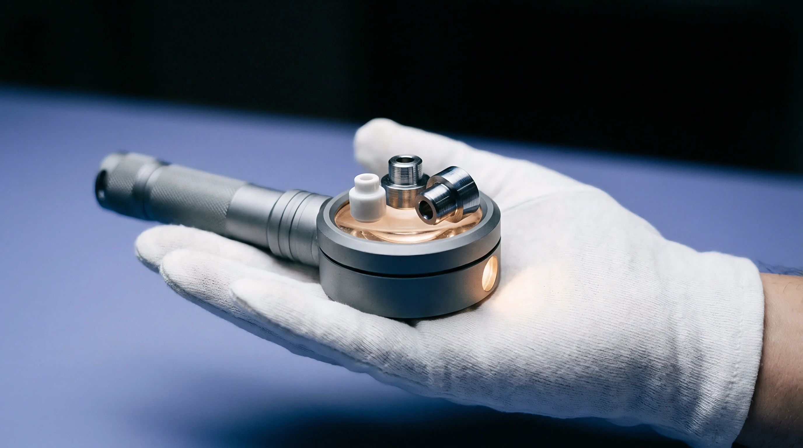
Quantifying the financial liability resulting from field-level microelectronic failures requires structured cost modeling. Because latent voiding manifests months or years after end-product distribution, a simple component defect easily escalates into multi-level commercial exposure. The total financial impact extends far beyond the replacement unit price of the packaged integrated circuit, requiring models to incorporate board scrap rates, field technician labor, express logistics, line shutdown penalties, and warranty reserve adjustments.
When field failure rates surpass acceptable quality levels, air freight and administrative costs accumulate rapidly while buyers face mandatory or voluntary product recall decisions. Microelectronics buyers calculate exposure scenarios across optimistic, expected, and catastrophic failure distributions to set contract indemnity caps during initial master supply agreement negotiations.

Field Return Rate Modeling for Thermal Aging
Establishing plating bath phosphorus caps prevents recurring lot rejections during substrate fabrication. Modeling long-term field return rates requires applying Weibull distribution functions calibrated with accelerated thermal aging data. Isothermal storage test results at one hundred fifty degrees Celsius map onto operational temperature profiles using Arrhenius acceleration equations.
A package lot exhibiting a two percent void area fraction at zero-hour inspection may follow a low failure slope for eighteen months before entering a rapid wear-out phase. Once vacancy coalescence reaches critical density across the package array, field returns spike exponentially. Financial models must account for this non-linear failure progression to avoid underestimating long-term warranty reserve requirements.

Financial Liability Sensitivity Analysis
Rework unit economics escalate exponentially once packaged integrated circuits are soldered onto complex printed circuit board assemblies. Replacing a twenty-dollar microelectronic component soldered onto a six-hundred-dollar automotive control unit costs significantly more than the bare IC value alone, making direct component replacement only the baseline tier of financial exposure.
| Cost Tier | Expense Category | Unit Calculation Metric | Total Financial Exposure (10k Units) |
|---|---|---|---|
| Tier 1 | Direct IC Component Replacement | 10,000 units @ $25.00/unit | $250,000 |
| Tier 2 | PCB Rework & Scrap Value | 10,000 boards @ $450.00/board | $4,500,000 |
| Tier 3 | Field Removal & Logistics Labor | 10,000 sites @ $120.00/site | $1,200,000 |
| Tier 4 | Root Cause DPA & Legal Arbitration | Fixed Engineering & Analytical Lab Fees | $180,000 |
| Total Unmitigated Exposure (Net of Recovery Caps) | $6,130,000 | ||
Consider a practical exposure calculation walking forward a single production quarter containing ten thousand deployed microelectronic modules. Physical laboratory analysis proves that seven percent of the batch contains severe interfacial voiding due to uncalibrated electroplating bath additives. Direct component replacement costs equal two hundred fifty thousand dollars.
However, field technician retrieval fees, board assembly scraping costs, express air freight, and technical failure analysis lab charges escalate total gross losses to over six million dollars. If the subcontract manufacturing agreement caps OSAT liability at one hundred percent of purchase order value, the buyer absorbs over five point eight million dollars in unrecovered losses.
The unresolved question remains whether standard supply agreements can legally enforce third-party component supplier contributions when an OSAT improperly validates incoming substrate metallization.


Resolution
Settling technical disputes over Kirkendall voiding requires pre-agreed arbitration protocols and shared laboratory testing frameworks. When field returns trigger commercial claims, OSAT management teams routinely dispute root causes, alleging improper field installation, over-temperature operation, or physical mishandling by the buyer. Establishing joint technical arbitration protocols before production commences eliminates lengthy legal stalemates that disrupt ongoing component supply chains.
Dispute resolution workflows rely on standardized failure verification pathways executed by mutually agreed independent analytical test laboratories. Establishing clear step-by-step procedures for sample handling, destructive physical analysis, and statistical confidence bounds ensures that both parties accept analytical findings without resorting to prolonged litigation.

Joint Failure Analysis Protocol Structure
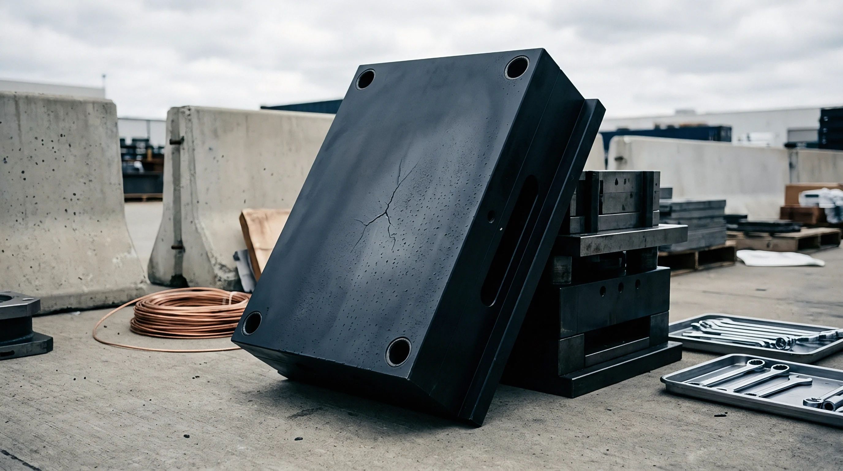
Independent third-party laboratory verification provides an objective basis for apportioning financial responsibility. Master service agreements must name three accredited microelectronics failure analysis laboratories authorized to conduct binding metallurgical assessments. When a latent failure dispute arises, the buyer and OSAT isolate affected production lots and submit random statistical samples directly to the selected laboratory.
The independent lab executes broad ion beam sectioning, field-emission SEM imaging, and EDX chemical mapping according to pre-scripted standards. The protocol tracks batch failure progression accordingly. If the lab detects interfacial void area fractions exceeding contractually specified limits alongside trace chemical contamination above baseline allowances, the finding binds the OSAT to financial indemnification rules set forth in the supply contract.
Commercial Settlement Execution Pathways
Negotiating recovery offsets against active production invoices maintains operational leverage while preserving vendor relationships. Microelectronics buyers rarely benefit from immediate litigation that halts component deliveries and damages critical supplier ties. Structured settlement agreements often convert validated indemnity claims into production price credits, extended warranty coverage, or dedicated OSAT capital investment in upgraded line metrology equipment.
Execution terms must outline precise schedule pathways for financial recovery. Recovery plans may spread total claim amounts across twelve to twenty-four billing cycles, preventing cash flow disruption for the OSAT while securing full financial recovery for the buyer. Binding settlement agreements should include audit provisions ensuring the OSAT installs real-time plating bath monitors and reflow atmospheric loggers to prevent systemic recurrence across future manufacturing runs.
Establishing technical clarity through standardized cross-sectioning and joint failure procedures converts ambiguous field claims into direct commercial resolution.