Tooling Amortization and Quality Control Protocols for Micro Hardware Runs
Micro hardware runs require amortizing soft tooling over exact batch counts while using one hundred percent optical metrology to catch thermal drift defects.


Die
Low-volume hardware production upends the usual economics of custom manufacturing. When a launch calls for five hundred or two thousand units instead of fifty thousand, building high-cavitation hardened steel tools sinks the project before it starts. A Class 101 mold in H13 tool steel hardened to 48 Rockwell C easily runs sixty thousand dollars.
Spread over a micro run of five hundred parts, that single NRE charge adds one hundred twenty dollars to every unit shipped. Soft tooling becomes the only realistic path ~ high-strength aluminum alloys, pre-hardened P20 steel, modular Master Unit Die frames, or hybrid additive inserts. But these faster tools come with mechanical trade-offs that directly hit part geometry and repeatability over the run.
Choosing 7075-T6 aluminum for a mold or stamping component cuts machining time by sixty percent compared to tool steel. It machines cleanly at high spindle speeds, dropping tool forces so bench technicians can hand-polish cavities in hours instead of days. Aluminum 7075-T6 also conducts heat at 130 Watts per meter-Kelvin, versus 24 Watts per meter-Kelvin for H13 tool steel.
That extra thermal transfer shortens molding cycles by twenty to thirty-five percent, trimming machine-hour rates on short runs. The catch is tool life. Yield strength in 7075-T6 drops under heat, causing localized compression around narrow ribs, core pins, and parting lines after just a few hundred cycles.
Aluminum 7075 tooling reduces non-recurring engineering expenditure by 62 percent compared to Class 101 steel when batch volume stays under 1,500 units.
Parting lines wear down and throw flash long before the main cavity faces lose their dimensions. In precision hardware, flash over 0.05 millimeters ruins assembly tolerances on micro-enclosures and internal frames. Core pins under 1.5 millimeters in diameter flex and erode quickly when running glass-filled polymers like nylon with thirty percent glass fiber.
Under high injection speeds, glass-filled resin acts like an abrasive slurry. Gate diameters open up within eight hundred cycles, altering fill pressure profiles, shifting weld lines, and pulling sink marks into cosmetic surfaces.
Modular Insert Engineering
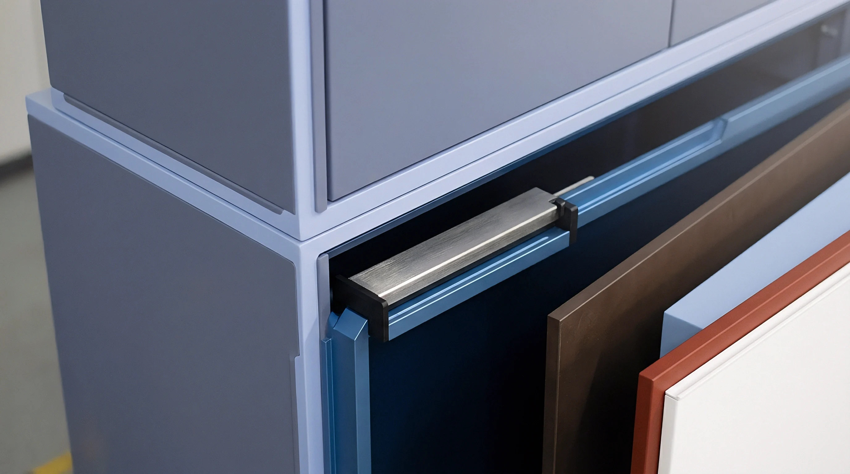
Standardized mold bases save upfront capital by keeping custom geometry inside interchangeable core and cavity inserts. Master Unit Die systems leave a permanent bolster plate in the machine to hold pocket inserts made from P20 steel or 7075 aluminum. That cuts tool steel volume by seventy percent, dropping raw material costs immediately.
Pocket fitment, however, brings its own problems. Thermal expansion differences between an aluminum insert and a steel bolster shift pocket clearances as the tool warms up. Once the aluminum insert hits an operating temperature of eighty degrees Celsius, its expansion coefficient of 23.4 micro-strain per degree Celsius outpaces the steel frame’s 11.5 micro-strain per degree Celsius.
That difference bows the cavity plane and opens tiny gaps along the parting line where polymer melt flashes out.
Tool wear in short runs is non-linear. Machine marks burnish off during the first fifty cycles, followed by a stable window, and then rapid breakdown under localized stress concentrations. This plays out on almost every pre-production run in Shenzhen.
Soft tools simply lack the compressive strength to take repeated hydraulic clamping day after day. If a five-hundred-unit batch goes onto an improperly calibrated ninety-ton press, platen deflection drives right into the mold base. The soft aluminum parting line deforms permanently, forcing operators to manually trim flash for the rest of the run.
| Tooling Material | Machining Lead Time | NRE Cost relative to H13 | Maximum Clean Cycle Life | Primary Failure Mode |
|---|---|---|---|---|
| Aluminum 7075-T6 | 5 to 8 days | 35 percent | 1,500 to 3,000 shots | Parting line flash and pin erosion |
| P20 Steel (Pre-hardened) | 10 to 14 days | 55 percent | 10,000 to 25,000 shots | Gate scarring with abrasive resins |
| NAK80 Steel (38-41 HRC) | 12 to 18 days | 70 percent | 50,000 shots | Minor hobbing under high clamp tonnage |
| SLA Resin Inserts | 2 to 3 days | 12 percent | 50 to 150 shots | Thermal cracking and structural shear |

Soft Tooling Material Performance
Choosing a tooling material sets both upfront spending and downstream rework risk. Short-run dies in unhardened P20 steel sit between expensive tool steels and soft aluminum. P20 yields 30 to 35 Rockwell C without needing secondary vacuum heat treatment after CNC milling.
It resists denting from stray runner scrap and holds up to moderate filler concentrations without rapid gate wash. Machining P20 takes forty percent longer than aluminum, raising NRE costs, but it remains far cheaper than fully hardened tool steel.
The decision comes down to total volume over the product’s lifespan. If a micro run covers the entire market volume for a specialized industrial sensor housing, an aluminum MUD insert gives the lowest landed cost. If the run is just a validation batch before scaling up, P20 steel lets the mold absorb five to ten extra runs without needing remachining.
Scrapping a soft tool after one small batch only makes economic sense when initial NRE savings outweigh the higher defect containment costs per unit.
An unhardened aluminum mold is often rated for five thousand shots without dimensional drift. That estimate assumes unfilled polypropylene resin, low injection pressures, draft angles over two degrees, and an operator who wipes cavity faces clean between cycles. The moment part specs demand zero-degree wall clearance, textured surfaces, or glass-filled polycarbonate, that aluminum cavity will degrade before eight hundred shots.
Quotes have to be weighed against actual part geometry and resin chemistry, not vague supplier promises.

Fixture
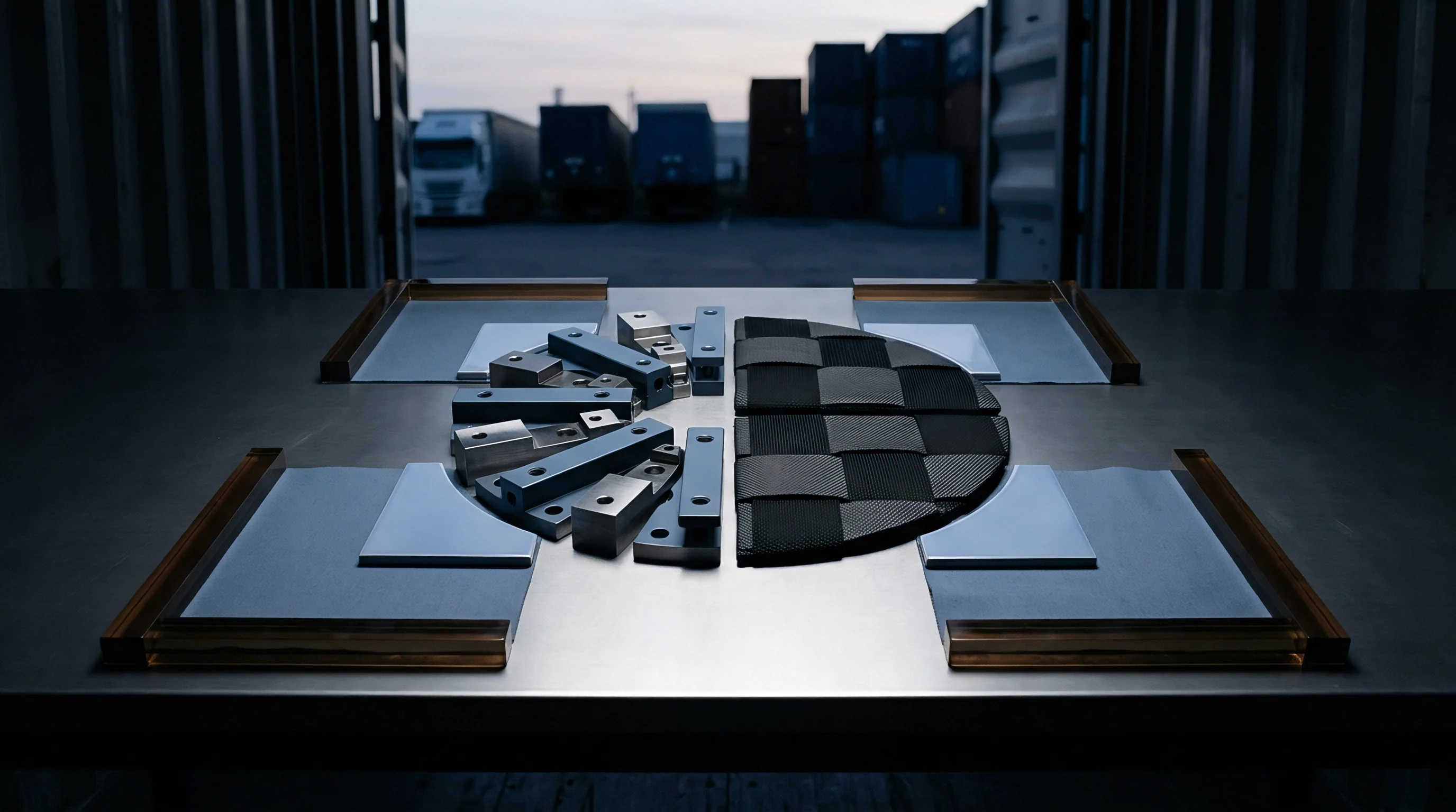
Workholding systems and positioning jigs dictate dimensional accuracy in micro hardware runs. Fully automated multi-axis positioning fixtures cost too much for low-volume production, so shops rely on manual clamping jigs, soft jaws, modular vacuum plates, and 3D-printed nests to hold machined enclosures and stampings during secondary operations or inspection. Manual handling introduces variance.
Small alignment errors, chips building up on locating pins, and uneven clamp pressure twist delicate micro parts, throwing off CMM reports and triggering assembly rejections.
Thermal stability in fixtures directly drives measurement consistency across shifts. Machine shops in Guangdong and Zhejiang see ambient temperatures swing twelve degrees Celsius between morning setup and peak afternoon heat. Aluminum expands at 23 micro-strain per meter for every degree of rise, meaning a 300-millimeter aluminum staging plate grows by 0.082 millimeters over a twelve-degree shift.
When target tolerances require positional accuracy within 0.03 millimeters, shop-floor heat alone drives parts past their allowable tolerance band.
Thermal equilibrium in unheated soft molds requires ten dummy shots before dimension logging begins.
Thermal Drift and Workholding Stability
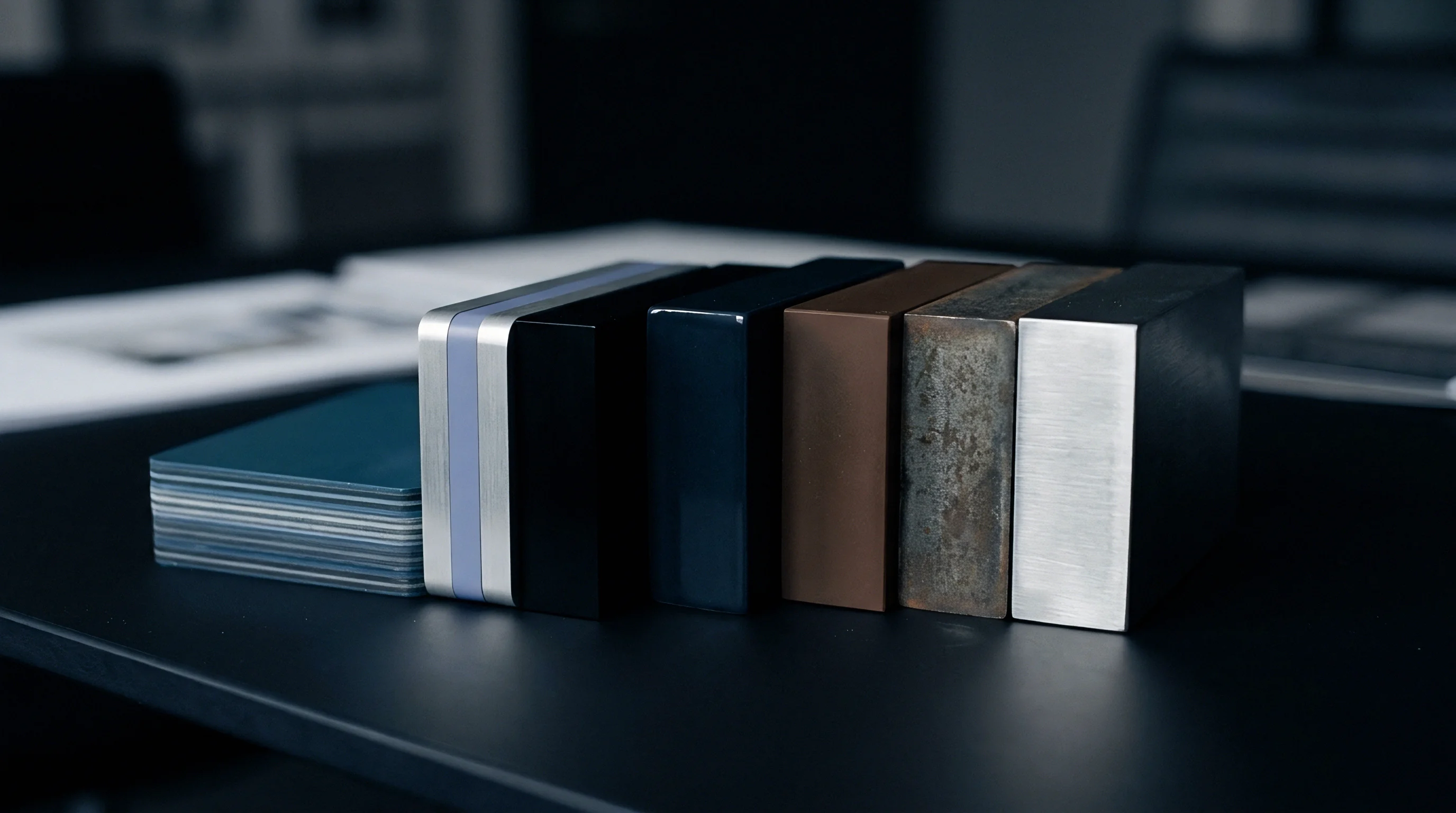
Controlling thermal expansion requires material matching or climate control in the inspection area. Using invar or carbon fiber composite plates for high-precision inspection jigs stops thermal movement, but quadruples material costs. The practical alternative is requiring a four-hour temperature soak for fixtures and parts before logging dimensions.
The metrology lab needs to hold twenty degrees Celsius within one degree, isolated from shop air. Skip this thermal normalization step, and you get false non-conformance reports ~ good parts rejected simply because they were measured on a hot fixture.
Inconsistent clamping force is another major cause of part distortion in short runs. Pneumatic toggle clamps exert predictable pressure, while manual thumb screws rely on operator feel. An over-tightened screw warps thin-walled micro-enclosures, pushing structural walls inward while the tool cuts.
When released, the metal springs back, pulling milled mounting holes out of position. Design rules for micro-run fixtures call for positive mechanical stops, torque-limiting handles, or vacuum hold-downs to keep clamping force constant regardless of who runs the bench.
| Workholding Type | Setup Time per Part | Repeatability Index | Initial Tooling Expense | Primary Variance Risk |
|---|---|---|---|---|
| Manual Soft Jaws (CNC) | 45 seconds | +/- 0.025 mm | $250 per set | Chip buildup under locating faces |
| Modular Vacuum Nest | 12 seconds | +/- 0.010 mm | $1,200 total setup | Vacuum seal degradation across run |
| Pneumatic Toggle Fixture | 18 seconds | +/- 0.015 mm | $1,800 total setup | Air line pressure fluctuation |
| 3D Printed Resin Nest | 30 seconds | +/- 0.060 mm | $80 per unit | Creep wear under mechanical load |

Datum Registration for Low Volume Assemblies
Setting reliable physical datums on short-run parts demands strict alignment between the CAD model, toolpaths, and inspection fixtures. Micro hardware rarely has large flat surfaces to reference. Operators often grab part corners or raw cast features as primary datums, carrying alignment errors into every subsequent operation.
Inspection protocols must enforce primary, secondary, and tertiary registration off precision dowel pins in ground locating holes rather than raw stock edges.
Part positioning depends entirely on clean contact surfaces. A single 0.04-millimeter aluminum chip trapped against a locating pin tilts a part in its nest, ruining hole perpendicularity across its entire length. Procedures should mandate blowing off workholding surfaces between loads.
Locating pins also need checking every two hundred cycles, because hardened steel dowels gradually enlarge soft aluminum locating holes and introduce play as the batch progresses.
Fixtures also have to absorb raw material variations from lot to lot. Extruded aluminum bar stock and die-cast blanks can vary by up to 0.15 millimeters across cross-sections between shipments. A rigid fixture that fits Lot A cleanly will pinch or throw off Lot B. Adjustable stops and spring-loaded edge finders accommodate those raw stock variations without pushing location errors into critical internal features.
A fixed clamping sequence keeps thin-walled housings from twisting. Standard instructions should require locking primary datum clamps before applying any secondary clamping force.

Gauge
Quality protocols built for high-volume manufacturing fall apart on micro hardware runs. Standard sampling plans like ISO 2859-1 General Inspection Level II rely on statistical assumptions built for large, uniform lots. For a batch of two hundred fifty custom machined housings, an ISO 2859-1 Normal Single Sampling Plan with an AQL of 1.0 calls for checking thirty-two units.
Accepting on zero defects and rejecting on one sounds clean on paper. But in a micro run, a defect cluster usually comes from a single short-lived incident ~ a dull cutter, a worn pin, or a manual deburring slip that ruins five consecutive parts.
Sampling a small batch gives very little statistical confidence that you’ll catch localized defects. If five bad components are sitting in a batch of two hundred fifty, a random thirty-two-part sample has a sixty percent chance of missing every single one. Shipping that lot risks assembly line shutdowns or field failures downstream.
Short runs need targeted quality protocols: high-density metrology on critical areas, explicit Critical-to-Quality mapping, and full non-destructive inspection on high-risk features.
Coordinate Measuring Machines offer high spatial accuracy, but they create severe bottlenecks. Running a full CMM program on a complex micro-enclosure can take twenty-five minutes per piece. On a three-hundred-part batch, full inspection would consume one hundred twenty-five machine-hours ~ longer than the entire CNC machining run.
Managing micro-run quality means balancing high-precision contact metrology with fast optical checks so inspection keeps up with machining.
ISO 2859-1 normal inspection level II generates unacceptable customer defect risk when applied to micro hardware batches under five hundred units.
Metrology Breakdown in Micro Batches
Standard Statistical Process Control relies on process capability metrics like Cpk, calculated over subgroup samples over time. Getting a valid Cpk takes at least one hundred twenty-five data points from a process running steadily at thermal and mechanical equilibrium. Micro runs of two hundred parts finish long before the process ever settles into equilibrium.
Calculating Cpk on a short batch just produces misleading numbers that mask actual quality, so process control has to move from trend tracking to hard, real-time limit checks.
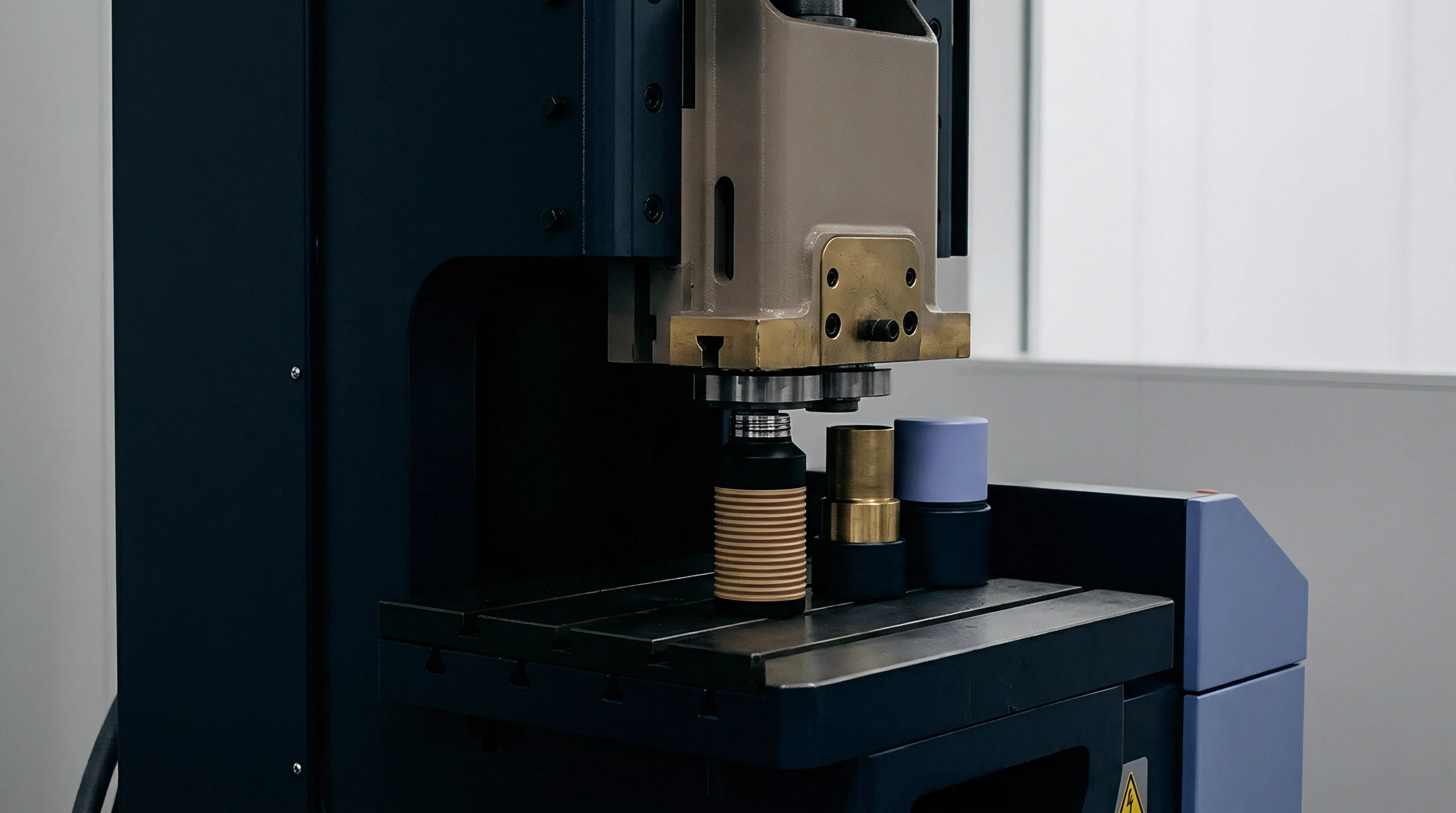
Optical profiling replaces statistical guesswork with direct physical measurement. Automated optical inspection tools and structured-light 3D scanners capture point clouds of a component in seconds. By projecting fringe patterns onto the part, a 3D scanner compares millions of surface points against the STEP model, producing color-coded deviation maps that instantly show wall thinning, warpage, sink marks, or misaligned holes.
It catches tool wear or clamping distortion long before manual caliper checks or height gauges spot a bad dimension.
First Article Inspection Execution
First Article Inspection under AS9102 forms the gate for approving micro-run production. The FAI requires verifying every dimension, radius, chamfer, surface finish callout, and material certificate on the drawing for the first off-tool part. Everything gets logged against ballooned prints in a formal dossier, and production stays paused until engineering signs off.
Running an FAI on soft tooling carries specific risks. One passing first article doesn’t guarantee part fifty will hold dimensions, given how fast aluminum or soft steel wears. FAI protocols for micro runs need intermediate inspection gates ~ checking, say, part fifty, part one hundred fifty, and the last part off the line ~ to confirm the tool stayed stable through the run.
- Complete balloon drawing preparation identifying all linear, angular, geometric, and material callouts.
- Calibrate coordinate measuring machine and optical profiling systems against traceable gauge blocks.
- Execute full dimensional sweep on the first off-tool component, logging actual values against nominal tolerances.
- Verify material certification sheets, plating thickness logs, and heat treatment callouts against order specifications.
- Document non-conformances on form three of the AS9102 dossier, specifying acceptable rework or tool modification steps.
- Secure dual engineering sign-off from both the supplier quality engineer and the buyer operating lead.
- Lock the verified first article in a sealed container on site to serve as the visual and physical golden sample for the run.
Optical Scanning Protocols
Optical systems measure 2D profiles, hole centers, pitch, and outer contours quickly, but struggle with deep pockets, blind tapped threads, or undercut channels. Contact touch probes on a CMM are still necessary to check deep internal features, thread pitch diameters, and narrow bore perpendicularities. A hybrid inspection approach hands outer features and hole patterns off to optical scanners, saving tactile CMM passes for critical internal dimensions.
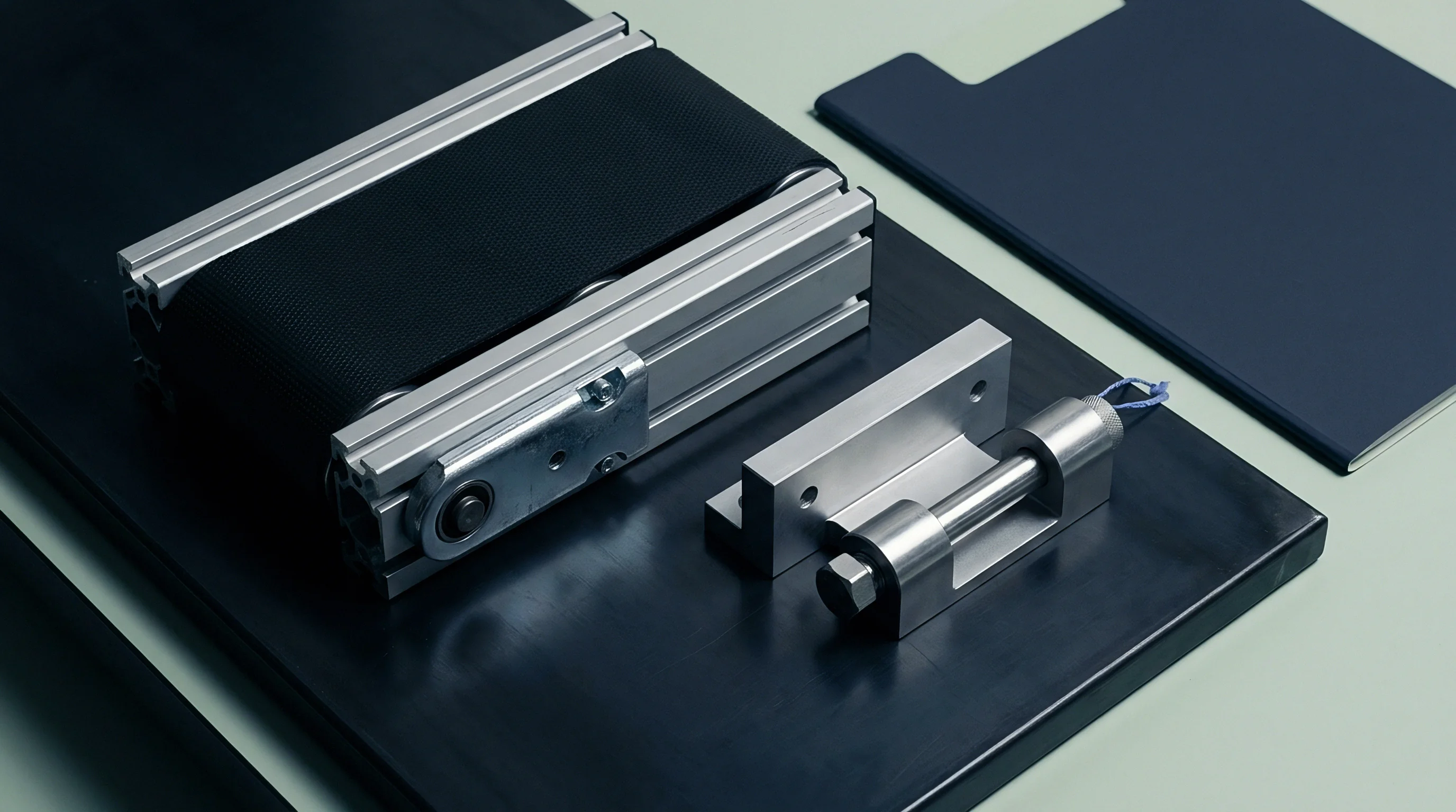
Hand gauges used on the shop floor must suit micro-hardware tolerances. Standard digital calipers carry an uncertainty of +/- 0.02 millimeters, making them unreliable for tolerances tighter than +/- 0.05 millimeters. Operators need plug gauges for bores, snap gauges for pins, and optical comparators for profile radii.
Clear visual pass-fail guides at the workstation cut down on operator measurement errors during routine checks.
Secondary CMM verification in Kunshan ran to four thousand dollars after an uncalibrated optical scanner accepted two hundred out-of-spec mounting frames.
Gauge Repeatability and Reproducibility (GRR) studies must validate specialized inspection fixtures before logging production data. A ten-part, three-operator GRR study isolates whether measurement variation comes from part differences or operator technique. If GRR variation exceeds fifteen percent of the total tolerance band, the setup cannot reliably separate good parts from bad.
Redesigning the fixture or switching to automated probes fixes measurement integrity and prevents scraping good parts on tight-tolerance jobs.

Defect
Defect containment in low-volume runs relies on fast root-cause identification and strict segregation of bad parts. On a five-hundred-piece run, scrap rates over five percent instantly wipe out profit margins. Unlike mass production, where minor tool tweaks amortize over tens of thousands of parts, micro-run defect trends must be caught within ten units to protect the batch.
Root-cause troubleshooting has to happen on the shop floor in real time, not during post-run reviews.
Short-run defects usually stem from setup instability, raw material lot variation, thermal expansion, or manual deburring slips. Techs on short runs often deburr micro hardware by hand using blades, pads, or small end mills, introducing human variance. An operator pushing too hard on an edge chamfer can easily strip off an extra 0.10 millimeters, ruining cosmetic edges or flattening gasket seal faces.
| Inspection Method | Measurement Speed per Part | Feature Capability | Capital Setup Cost | Optimal Batch Size Range |
|---|---|---|---|---|
| Contact CMM (Touch Probe) | 15 to 30 minutes | Deep bores, internal CTQs, GD&T | $50,000 to $120,000 | 1 to 50 units (Sampling) |
| 3D Structured Light Scanner | 1 to 3 minutes | Full surface profile, warpage maps | $35,000 to $80,000 | 50 to 500 units (100% Scan) |
| Automated Optical Inspection | 5 to 15 seconds | 2D profile, hole pitch, flat geometry | $15,000 to $40,000 | 100 to 2,500 units |
| Manual Mechanical Gauges | 30 to 90 seconds | Specific bore diameters, outer steps | $500 to $2,000 | 10 to 250 units (Operator checks) |
Non Conformance Containment Systems
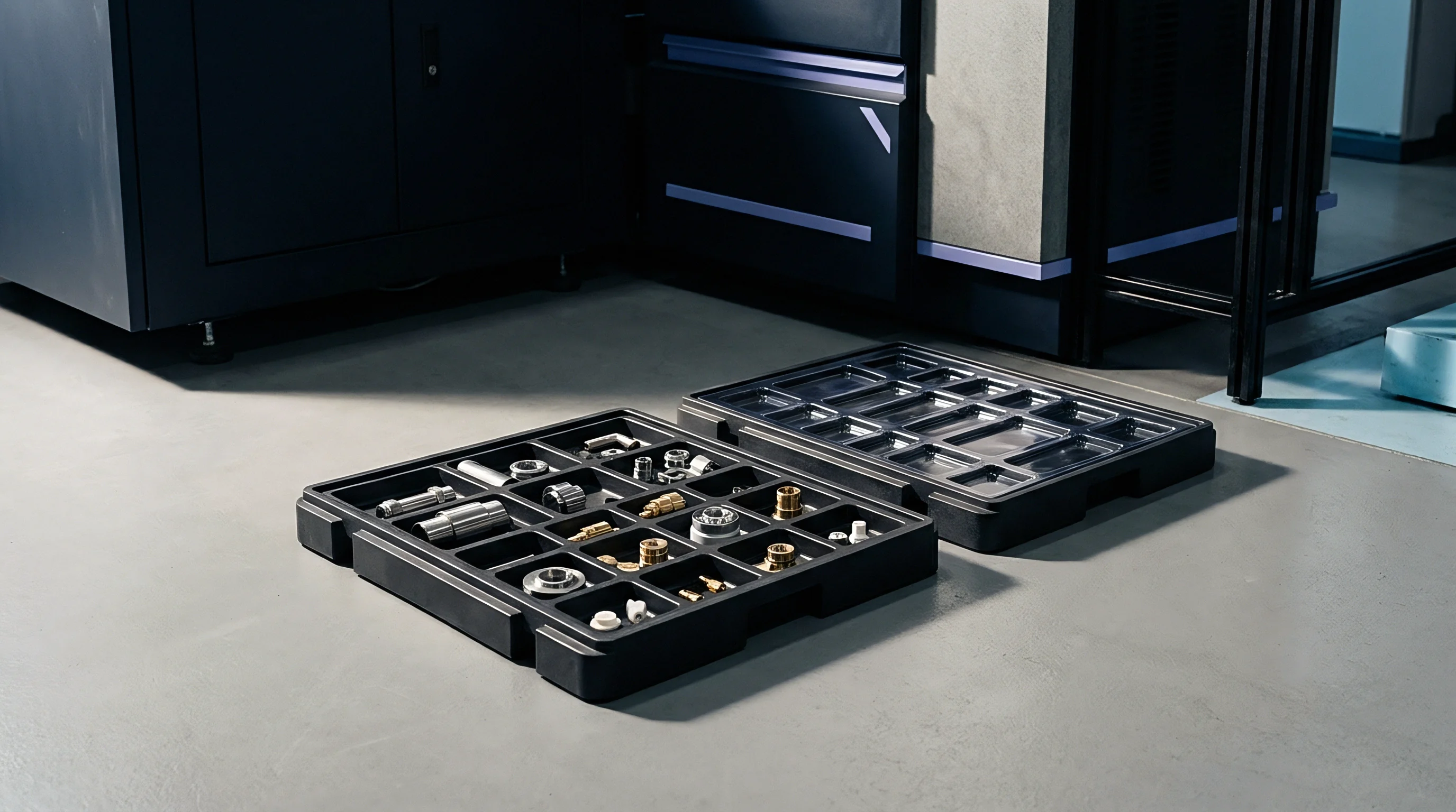
Containing non-conforming parts requires pulling suspect pieces off the line immediately into quarantine cages. Red-tag protocols mandate that any part off drawing spec leaves the cell instantly. In low-cost supplier shops, operators often set questionable parts on workbenches right next to good stock, causing mix-ups during final packing.
Procedures must require locked red bins at every work cell, with keys held strictly by the quality manager.
Reworking out-of-spec micro hardware takes precise secondary workholding. If two hundred aluminum brackets have undersized holes from cutter wear, re-reaming means picking up the original datums on every single piece. If the secondary fixture introduces just 0.03 millimeters of positioning error, the reamer cuts off-center holes and turns salvageable parts into scrap.
Deciding whether to sort, rework, or remake requires factoring in setup time, labor costs, and schedule impact.
- Quarantine Segregation locks suspect components in physical red bins immediately upon non-conformance detection.
- Dimensional Logging records exact deviations on non-conformance reports to track wear trends.
- Disposition Authorization requires joint engineering and quality lead approval before attempting part rework.
- Rework Validation subjects hundred percent of modified components to full FAI dimensional sweeps.
- Scrap Scuttling physically deforms unrepairable parts to prevent unauthorized mixing into shipping inventory.
Sorting Economics for Short Runs
Sorting a short run to save usable parts makes economic sense when schedule deadlines outweigh replacement costs. If remachining parts takes three weeks, paying technicians for hundred-percent manual inspection keeps the delivery schedule intact. Sorting costs should be charged against supplier quality metrics to track true unit costs.
But if sorting shows yields dropping below eighty-five percent, scrapping the batch and re-running on fresh tooling is usually cheaper than sorting through questionable parts.
Suppliers often ask to ship out-of-spec parts under engineering waivers or concessions. On micro-hardware runs, accepting non-conforming dimensions demands careful downstream evaluation. A hole shifted by 0.05 millimeters might still clear a bolt, but it could bind internal gears or flex a PCB during assembly.
Waivers should never be granted on structural wall thicknesses, thermal interfaces, or primary datums.
Tracking defects across micro runs relies on Pareto categorization. Logging failure modes over multiple small batches highlights recurring shop issues ~ like raw material flaws, uncalibrated machines, or gaps in operator training. Fixing those root causes improves first-pass yield on future micro runs, stabilizing piece costs and delivery schedules.
Section 8.4 of the standard supply agreement specifies that any non-conforming lot exceeding a three percent threshold triggers an immediate production stop and supplier-funded third-party sorting protocol.

Settlement
Contracts for short-run production need clear separation between non-recurring engineering (NRE) fees, piece prices, and scrap allowances. Suppliers often try to embed soft tooling costs into component unit prices ~ quoting, say, twenty dollars a part for five hundred pieces to hide a ten-thousand-dollar tool cost. If the tool wears out early and yields only four hundred good parts, disputes immediately flare over tool ownership, remaining amortization, and rework costs.
Unbundling NRE tooling charges from unit prices protects the buyer. Tooling should be handled on a separate, milestone-based purchase order ~ paying forty percent on PO release, thirty percent on T1 sample approval, and thirty percent on final lot acceptance. This structure maintains financial leverage through tool qualification.
If a soft tool fails to produce conforming parts during the run, holding the final payment forces the supplier to correct tool geometry on their own dime.
Amortization accounting must define tool life in physical cycle counts, not calendar days. A soft aluminum mold rated for two thousand cycles amortizes its cost across those two thousand potential shots. If a buyer runs five hundred units, they consume twenty-five percent of the tool’s life; the remaining seventy-five percent stays buyer property for future batches.
Contracts should explicitly require the supplier to clean, maintain, and store buyer-owned tooling in ready-to-run condition for at least twelve months after batch completion.
Tooling amortization line items embedded within unit prices conceal true scrap costs when short-run dies degrade early.
Amortization Structure Mechanics
Managing short-run financial risk means setting clear contract terms for scrap and setup waste. Machine setup and thermal stabilization consume raw material on every run. Setting up a CNC mill or mold can take ten to twenty raw parts before dimensions stabilize.
Quotes need to list setup scrap allowances as a line item rather than burying them in unit costs, preventing suppliers from deducting setup scrap from the delivered part count.
Tooling custody and transfer rights are a frequent friction point in cross-border manufacturing. Suppliers in Asian hubs often hesitate to release soft tools, citing custom modifications or unpaid balances. Contracts must state clearly that all dies, inserts, fixtures, and nests funded under NRE agreements remain the sole physical and intellectual property of the buyer, with explicit rights to audit, inspect, or retrieve tools within forty-eight hours of written notice.

Tooling Ownership Transfer Terms
Reconciling final invoices requires checking delivered, conforming quantities against inspection reports and milestone sign-offs. Final settlement should only happen after parts pass incoming QC at the buyer’s facility or an independent inspector verifies the lot on site. Deducting sorting fees, inspection labor, and rework costs directly from the final invoice keeps commercial disputes short.
Commercial transparency takes open-book pricing on raw materials, machine rates, assembly labor, and inspection overhead. When suppliers know a low-volume run is a stepping stone to mass production, they are far more open to transparent margins. Standardizing amortization tracking, quality gates, and payment milestones aligns factory incentives with buyer specs, keeping short runs on budget and up to standard.
How does a buyer effectively calculate the long-term cost impact of physical tool wear when deciding whether to re-machine an aging aluminum insert or fund a new steel tool for subsequent micro runs?