Micro Batch Hardware Procurement Mechanics for Low Volume Production
Micro-batch hardware procurement requires locking CAD packages, using C=0 sampling plans, and amortizing setup NREs to control unit economics.

Bench
A thirty-layer printed circuit board assembly designed for low-power edge compute resting on a diagnostic station with three unpopulated decoupling capacitor pads reveals an unverified sub-tier bill of materials modification. Micro-batch production runs, typically spanning fifty to five hundred units, exist in an operational space between prototype hand-assembly and automated volume manufacturing. Engineering choices made during initial prototype bring-up often fail when transferred to low-volume contract manufacturing setups where automated optical inspection programs and dedicated surface-mount technology feeders are economically unviable.
Transitioning from benchtop validation to structured small-scale assembly requires explicit locking of Gerber files, bill of materials lines, and mechanical spatial fit models. Standard prototype practices permit manual component substitution, wire jumpers, and unrecorded firmware patches. Hardware manufacturing in micro-batches penalizes these informal adjustments.
Setup costs, line changeover times, and non-recurring engineering charges dominate unit economics when total order volumes remain small. Line balance changes rapidly.

Transitioning Prototypes to Assembly CAD Packages
Engineering teams frequently deliver computer-aided design files containing non-standard component footprints or obsolete active silicon packages to production workshops. Contract assembly partners handling low volume runs lack the engineering overhead to re-layout printed circuit board trace routings or modify assembly drawings. The buyer prepares complete fabrication and assembly packages containing fully specified IPC-A-610 Class 2 or Class 3 acceptance criteria, exact component part numbers, and gerber files with explicit solder mask dams.
Manual placement of surface-mount components becomes impracticable at fine pitch scales.
Component selection directly impacts production feasibility when automated pick-and-place setup fees are bypassed in favor of semi-automated assembly. Ultra-fine pitch ball grid array packages with ball pitches below zero point four millimeters demand precise stencil apertures and automated placement, regardless of batch size. Substituting qfn packages with leaded quad flat packages simplifies visual inspection and hand-rework steps on small production runs without sacrificing functional density.

Validation Protocols across Sub-Thousand Unit Runs
Establishing acceptance criteria across low-volume builds relies on clear physical references. The golden sample set-piece serves as the physical benchmark against which surface finish, cable routing, solder fillet appearance, and label positioning are measured. Golden sample units receive full functional validation, environmental stress testing, and dimensional inspection before receiving buyer seal and signature on the workshop floor.
| Build Stage | Minimum Sample Size | Tooling Type | Dimensional Tolerance Band | Functional Yield Floor |
|---|---|---|---|---|
| Engineering Validation | 5 to 10 units | Soft tooling / 3D printing | Plus or minus 0.30 mm | 80 percent |
| Design Validation | 20 to 50 units | Rapid aluminum tooling | Plus or minus 0.15 mm | 90 percent |
| Micro-Batch Production | 100 to 500 units | Bridge aluminum / NAK80 steel | Plus or minus 0.05 mm | 98 percent |
Tolerance stack-up calculations become critical when combining injection-molded enclosures, CNC-machined internal frames, and surface-mounted printed circuit boards. Standard prototype validation tests individual part geometries in isolation. Micro-batch validation tests cumulative assembly fits, accounting for thermal expansion variations and manufacturing tolerances across distinct material suppliers.
Whether suppliers absorb nominal setup recalibration fees during second-pass board bring-up remains an open negotiation point in contracts missing explicit revision thresholds.


Fixture
Soft tooling strategies form the foundation of low-volume hardware production by eliminating the six-figure expenditures and sixteen-week lead times associated with hardened steel production molds. Aluminum molds machined from 7075-T6 alloy or NAK80 tool steel provide a production bridge capable of delivering one thousand to ten thousand shots before cavity wear compromises part dimensions. Rapid tooling choices dictate whether a micro-batch run yields consistent mechanical enclosures or requires manual fitting during final assembly.

When Do Rapid Tooling Materials Fail Micro Batch Tolerances?
Aluminum tooling exhibits thermal conductivity rates nearly three times higher than P20 tool steel. Higher thermal conductivity speeds up injection molding cycle times, but accelerated thermal expansion increases part shrinkage variations across short production runs. Tool operators must maintain precise mold temperature control systems to prevent part warping and wall thickness variations.
Tooling quality directly governs acceptable part yields across the build.
Polyurethane casting using silicone molds offers an alternative for production quantities below fifty units per month. Silicone molds degrade rapidly under exposure to exothermic polyurethane resin reactions, experiencing dimensional expansion and surface degradation after twenty to thirty cycles. Mold degradation alters mating rib alignments and snap-fit retention forces across sequential casting batches.
- Silicone Mold Cavity Thermal Degradation creates volumetric swelling beyond nominal engineering limits after twenty-five casting cycles under high-temperature polyurethane resins.
- Aluminum Core Pin Bending results from unbalanced injection pressures on thin-walled geometry when cycle times drop below machine steady-state thresholds.
- Manual Insert Alignment Drift introduces flash along parting lines when operators fail to clear resin residue between short runs.
- Ejection Pin Surface Galling damages soft aluminum ejector plates after fifty dry cycles without adequate lubrication.
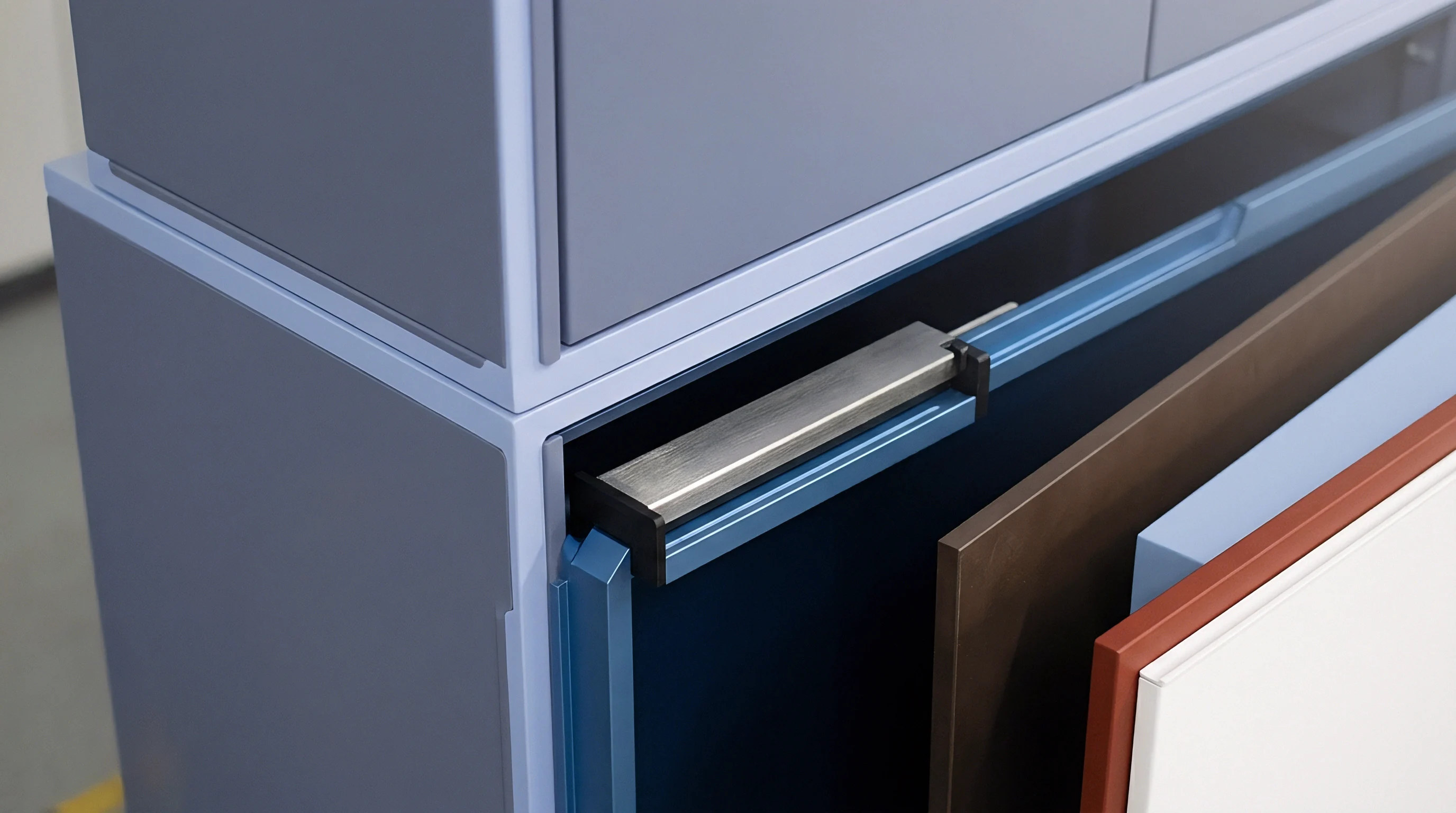
Aluminum versus Steel Mold Life Mechanics
Evaluating tool steel selection requires balancing tooling NRE costs against anticipated product design iteration lifecycles. High-mix hardware products frequently undergo enclosure modifications after initial field deployment. Machining structural changes into an aluminum mold takes hours on a three-axis CNC mill, whereas modifying hardened H13 steel tools demands electrical discharge machining and extended downtime.
Uncorrected dimensional drift increases yield losses as production continues.
Selecting unhardened tooling alloys without thermal calculation distorts mating enclosures and creates secondary machining expense during final enclosure assembly.

Stock
Component procurement for micro-batch hardware manufacturing operates under severe structural constraints imposed by global semiconductor supply chains. Tier-1 component distributors establish minimum order quantities and standard factory package sizes designed for volume buyers. A project requiring two hundred microcontrollers must navigate purchasing full tape-and-reel quantities of two thousand five hundred units or sourcing partial quantities through secondary broker channels.

BOM Allocation and Minimum Order Quantity Distortion
Procuring raw silicon and passive components through unauthorized brokers exposes low-volume projects to gray-market risks, including remarkeable microcontrollers, recycled integrated circuits, and counterfeit passives. Broker stock often lacks lot traceability documents, reel moisture barrier packaging, and factory date codes. Exposure to moisture damages unsealed integrated circuits during reflow soldering.
Trapped moisture causes delamination and cracking in unsealed ICs during reflow.
Managing minimum order quantity distortions requires structured bill of materials consolidation. Engineering teams standardize passive component package sizes to 0603 or 0805 geometries across all circuit blocks, allowing bulk purchase of single resistor and capacitor reels that cover multiple board functions. Active silicon selections prioritize high-volume parts actively used by tier-1 automotive or consumer hardware manufacturers to ensure stock availability through authorized franchised distribution.
BOM risk concentrates in single-sourced active silicon where lead time uncertainty exceeds the build cycle length.
| Sourcing Channel | Lead Time Variance | Minimum Order Quantity | Counterfeit Risk Index | Lot Traceability Depth |
|---|---|---|---|---|
| Franchised Direct Distribution | 12 to 26 weeks | Standard Factory Pack (1,000+) | Zero | Full Certificate of Conformance |
| Authorized Catalog Distributors | 1 to 3 days | Single Unit / Cut Tape | Very Low | Traceable to Manufacturer |
| Qualified Independent Brokers | 1 to 2 weeks | Negotiated Partial Lots | Moderate | Third-Party Test Report |
| Open Market Spot Traders | 1 to 5 days | Variable Bulk Lots | High | Unverified Visual Inspection |
Mitigating Secondary Market Counterfeit Exposure
When short production timelines compel purchasing components outside franchised distribution, rigorous incoming component inspection protocols are mandatory. Destructive decapsulation, X-ray inspection of lead-frame die wire bonds, and optical surface test sweeps identify remarkeable components before mounting them onto expensive printed circuit boards. Third-party testing laboratories charge flat fees per component lot, adding fixed overhead that must be distributed across the small batch volume.
Component lead times fluctuate significantly across secondary market options.
Partial reels and leader tails increase material scrap rates during setup.
Authorized distribution channels frequently refuse to release partial reel quantities due to factory pack constraints.


Floor
Selecting a contract manufacturer for small-volume production demands evaluating workshop floor operational layouts rather than corporate marketing dossiers. Large tier-1 EMS providers prioritize continuous automated lines running thousands of identical assemblies per shift. Low-volume hardware projects assigned to volume facilities face line preemption, key operator reassignment, and inflated setup fees whenever high-volume clients request line capacity.

Contract Manufacturing Selection for High Mix Low Volume Runs
Mid-sized, specialized high-mix low-volume contract assembly partners maintain flexible line setups, specialized hand-soldering stations, and offline functional testing cells. These facilities calculate pricing structures around setup changeover fees, manual labor hours, and specialized engineering support rather than pure component placement speeds. Line allocation contracts must secure guaranteed engineering support hours and dedicated line space during scheduled assembly runs.
Setup charges for automated SMT placement lines drop unit margins by forty percent when lot sizes fall below two hundred units.
Golden sample approval fixes the production baseline before full assembly begins.

Standard Operating Procedure Deployment for Low Volume Line Layouts
Operators on micro-batch assembly lines handle varied assembly tasks compared to operators on dedicated volume lines. Clear visual work instructions, localized torque settings on automated drivers, and poka-yoke mechanical alignment jigs prevent manual assembly errors. Assembly instructions must be localized into the native language of the line technicians and physically displayed at each work station.
- Issue localized assembly drawing packs containing explicit torque limits, critical dimension indicators, and adhesive curing cycles.
- Audit factory ESD grounding systems, temperature controls, and operator station lighting prior to setup.
- Conduct a supervised golden sample assembly sequence on the line to establish cycle time baselines.
- Validate offline functional test stations against known pass and fail calibration boards before releasing production materials.
- Lock component reels and mechanical parts into dedicated, labeled kitting bins to prevent batch contamination.
Small build quantities amplify the relative cost of assembly errors.
A line item specifying buyer ownership of custom offline test fixtures transfers tool custody immediately upon completion of factory acceptance testing.


Gate
Quality control strategies designed for volume manufacturing fail when applied to micro-batch production environments. Standard Acceptable Quality Limit sampling plans under ISO 2859-1 or ANSI/ASQ Z1.4 rely on statistical probability models that require lot sizes of several thousand units to achieve statistical confidence. In a batch of one hundred units, extracting a random sample of thirteen units under standard inspection levels allows zero defects for acceptance, converting statistical sampling into a de facto pass-fail gate for the entire batch.

Zero Acceptance Sampling Mechanics in Micro Batch Runs
Zero-acceptance sampling plans, specifically Squeglia C=0 tables, optimize quality verification for small production runs. C=0 plans structure inspection sampling sizes such that finding a single defect in the selected sample leads to immediate rejection of the entire lot. This approach focuses inspection effort directly on critical non-conformances without requiring excessive sample counts that destroy small lot yields.
According to ISO 2859-1 standards, switching from normal to tightened inspection occurs automatically when two consecutive batches suffer lot rejection.
First article inspection establishes dimensional and functional compliance before releasing the lot.
- C Zero Acceptance Plans apply when defect tolerance is zero and sample sizes must stay below fifteen percent of total lot size under ANSI/ASQ Z1.4 rules.
- One Hundred Percent Functional Testing serves as the baseline requirement when micro-batch assembly costs exceed component replacement expenses.
- First Article Inspection Protocols verify tooling alignment and dimensional stability on the initial five units before full batch processing proceeds.
- Destructive Weld and Crimp Testing limits sample pull counts to three units per sub-lot to preserve total order yield.

Functional Test Rig Deployment at Low Scale
Designing custom offline functional test fixtures provides continuous quality verification without the immense expense of automated bed-of-nails in-circuit test equipment. Custom functional test boxes combine pogo-pin programming interfaces, microcontroller-driven sensor inputs, and power consumption measurement circuits to validate fully assembled circuit boards in under sixty seconds.
Test fixtures require periodic calibration against known reference standards.
Inspection rigor shifts directly toward first article verification when production run length drops below assembly line stabilization thresholds.


Arithmetic
Landed unit cost calculation for low-volume hardware requires total absorption of all non-recurring engineering charges, tooling expenses, setup fees, and oversight costs. Volume production masks setup fees across tens of thousands of units, making piece-part component costs the dominant cost driver. Micro-batch economics are dictated by fixed setup overheads and yield loss sensitivity.

Non Recurring Engineering Amortization and Unit Cost Scaling
Evaluating the financial impact of batch size variations requires comparing cost structures across realistic micro-batch order quantities. Fixed engineering costs, including surface-mount technology stencil creation, pick-and-place programming, offline test fixture fabrication, and rapid aluminum tooling, remain constant whether producing two hundred units or one thousand units.
Setup and tooling overheads dominate unit economics in small runs.
| Cost Element | 200-Unit Run Cost per Unit (USD) | 1,000-Unit Run Cost per Unit (USD) | Cost Sensitivity Category |
|---|---|---|---|
| Printed Circuit Board Fabrication | 14.50 | 6.20 | Volume Batch Discount |
| Component BOM Cost | 68.00 | 52.00 | Distributor Tier Pricing |
| Rapid Aluminum Tooling (NRE) | 32.50 | 6.50 | Fixed Amortization |
| SMT Line Setup & Stencil (NRE) | 9.00 | 1.80 | Fixed Amortization |
| Offline Test Rig Fabrication (NRE) | 12.50 | 2.50 | Fixed Amortization |
| Assembly Labor & Functional Test | 22.00 | 16.00 | Labor Efficiency Curve |
| Air Freight & Customs Duties | 11.50 | 8.40 | Volumetric Shipping Tier |
| Scrap Allocation (5% vs 2%) | 8.50 | 1.85 | Yield Loss Curve |
| Assumptions: Single PCB board, custom aluminum enclosure, initial tooling build, air express delivery to Western Europe. Total landed unit cost drops from 178.50 USD at 200 units to 95.25 USD at 1,000 units. | |||

Landed Economic Sensitivity in Low Scale Electronics Production
Scrap rate variations impact micro-batch runs disproportionately. A five percent defect rate on a ten thousand unit run represents manageable rework costs absorbed within standard operational margins. A five percent defect rate on a two hundred unit run depletes safety stock, forfeits component price breaks, and requires secondary short-run setups that double total engineering expenses.
Relying on air freight quickly erodes project profit margins.
Air freight costs double unit transportation overhead when production delays force shipments onto expedited flight schedules.
Unplanned scrap directly reduces realized operating margins.
Calculating scrap rates across small batch sizes demands direct inclusion of setup loss, component reel tail loss, and destructive inspection samples.