Stress Coupled Atomic Flux Modeling in High Density Flip Chip Interconnects
Stress-coupled atomic flux modeling identifies package current and thermal limits before premature microbump voiding drives catastrophic field warranty returns.


Divergence

Thermomigration and Electromigration under Triaxial Mechanical Confinement
Modern flip chip ball grid arrays operating at bump pitches below 80 micrometers concentrate electrical currents, mechanical restraint, and thermal dissipation into volumes under 10,000 cubic micrometers per pillar. Microbumps constructed from lead-free alloys such as tin-silver (Sn-Ag) experience mass transport driven simultaneously by high current density, steep temperature gradients, and localized hydrostatic stress gradients. Atomic flux divergence models that isolate electromigration without solving the coupled stress and thermal fields predict failure locations that deviate completely from accelerated life test outcomes.
The chemical potential of a diffusing metallic atom inside the bump depends on the local electron wind force, the thermal kinetic activation, and the gradient of hydrostatic stress within the crystalline matrix.
Hydrostatic tension lowers the activation energy for atomic vacancy formation. Hydrostatic compression elevates it. High current densities entering the bump through thin under-bump metallization traces generate severe current crowding at the entrance corner, producing localized Joule heating.
The localized temperature rise sets up a thermal gradient exceeding 1,000 degrees Celsius per centimeter across a 30-micrometer tall solder volume. The thermal gradient drives tin atoms away from hot spots toward cold spots through thermomigration, while the electron wind pushes atoms along the path of electron flow through electromigration. The resulting accumulation or depletion of metal creates localized volumetric changes against the rigid confinement of silicon dies, copper pillars, and cured underfill resins, establishing intense internal stress gradients that oppose or amplify the initial transport forces.
Coupled flux calculations confirm that a thermal gradient of 1,200 degrees Celsius per centimeter generates thermomigration forces equal in magnitude to an electrical current density of 10,000 amperes per square centimeter.
Analytical treatments of flip chip interconnect failure rely on solving the generalized atomic flux equation. Total flux vector J combines chemical diffusion, electromigration drift, thermomigration movement, and stress migration drift into a single continuity relation. The equation takes the unified form:
J = -(D C / (k T)) (grad(mu))
In this framework, D represents the effective atomic diffusion coefficient, C represents the instantaneous atomic concentration, k represents the Boltzmann constant, and T represents absolute temperature. Expanding the chemical potential gradient reveals four distinct driving components:
J = -D grad(C) + (D C / (k T)) (Z_eff e E) – (D C Q_star / (k T^2)) grad(T) + (D C Omega / (k T)) grad(sigma_h)
Here, Z_eff represents the effective charge number, e represents elementary electron charge, E represents electric field vector, Q_star represents the heat of transport, Omega represents atomic volume, and sigma_h represents hydrostatic stress, defined as one-third the trace of the stress tensor. The sign convention dictates that atoms migrate toward regions of higher hydrostatic tension, thereby relaxing localized compressive stress fields.

Constitutive Interactions across Flip Chip Geometries
The boundary conditions of high-density interconnect packages impose mechanical constraints missing from unconstrained bulk wire geometries. The silicon die exhibits a coefficient of thermal expansion near 2.6 parts per million per Kelvin. Solder bump alloys exhibit thermal expansion values between 20 and 24 parts per million per Kelvin.
The organic packaging substrate ranges between 14 and 17 parts per million per Kelvin. Capillary underfills, introduced to alleviate shear fatigue, display coefficients between 25 and 35 parts per million per Kelvin below their glass transition temperature. Cooling from the solder reflow peak of 245 degrees Celsius locks the entire assembly into a state of severe triaxial residual stress before electrical power connects to the circuit.
When current passes through the microbump, the localized current crowding zone exhibits divergence of atomic flux. Vacancies coalesce where the divergence of atomic flux is positive. Atoms accumulate where the divergence of atomic flux is negative.
At the cathode corner where current exits the under-bump metallization into the solder, electromigration and thermomigration typically act in concert, evacuating solder atoms into the bulk. The evacuated mass leaves behind a vacancy supersaturation that yields mechanical tensile stress, pulling additional vacancies toward the corner while generating compressive back-stress downstream. If the surrounding underfill and silicon rigidly prevent volume relaxation, the induced gradient of hydrostatic stress opposes the electron wind, establishing a counter-balancing stress migration flux that slows void growth until local intermetallic compound boundaries fail under tension.
A package designer attempting to optimize bump pitch without integrating stress coupling risks immediate qualification failure under JEDEC standard JESD22-A154. Void nucleation models that neglect hydrostatic stress gradients overestimate the time to void initiation by a factor of three to four. The mechanical constraint converts current-induced mass loss into localized micro-cracking rather than uniform void growth, changing the physical kinetics of interconnect degradation.

Kinetics

Vacancy Continuity and Multi-Physics Solvers
Predicting mechanical void nucleation and intermetallic compound cracking requires coupling electrical Laplace conduction, transient Fourier thermal diffusion, mechanical equilibrium, and vacancy continuity into a single iterative simulation framework. The continuity equation governs the temporal evolution of vacancy concentration C_v throughout the interconnect volume:
d(C_v) / dt + div(J_v) = G_v
In this expression, J_v is the vacancy flux vector, defined as the negative of the atomic flux vector J, and G_v represents the generation and annihilation rate of vacancies at internal microstructural sinks such as grain boundaries, dislocation cores, and intermetallic interfaces. The generation-annihilation term operates via the classic vacancy relaxation relation:
G_v = -(C_v – C_v0 exp(Omega sigma_h / (k T))) / tau_v
Here, C_v0 denotes thermal equilibrium vacancy concentration under stress-free conditions, while tau_v represents the characteristic relaxation time for vacancy equilibrium. When localized hydrostatic stress sigma_h rises to substantial compressive values, the local equilibrium vacancy concentration drops sharply, driving vacancy annihilation and producing volumetric lattice swelling. Tensile hydrostatic stress elevates equilibrium vacancy concentration, maintaining a continuous thermodynamic sink that absorbs vacancies until micro-voids nucleate.
Solving these coupled partial differential equations demands staggered or fully monolithic numerical techniques. Finite element solvers evaluate the electrical field first, calculating current density distribution J_e = sigma_elec E. The resistive dissipation per unit volume q_dot = J_e^2 / sigma_elec passes directly into the thermal solver as an internal heat source term. The computed temperature field establishes non-uniform material properties and generates thermal strain tensors epsilon_th = alpha delta_T I, which combine with mechanical loads to determine the stress tensor sigma_ij via elastic-plastic or creep constitutive formulations.
Finally, the atomic and vacancy flux continuity equations run across the updated spatial mesh to evaluate divergence fields.
| Physical Property | Bulk Beta-Sn | Cu6Sn5 Intermetallic | Copper Pillar | Capillary Underfill |
|---|---|---|---|---|
| Resistivity (nano-ohm meter) | 135 | 175 | 21 | 1.0 x 10^18 |
| Thermal Conductivity (Watts per meter Kelvin) | 62 | 34 | 385 | 0.7 |
| Effective Charge Number (dimensionless) | -18 | -6 | -5 | 0 |
| Heat of Transport (electron-volts) | -0.0094 | -0.0042 | -0.0020 | 0 |
| Activation Energy for Self-Diffusion (electron-volts) | 0.82 | 0.98 | 1.25 | 2.10 |
| Coefficient of Thermal Expansion (ppm per Kelvin) | 21.5 | 16.3 | 16.8 | 28.0 |
| Young’s Modulus (Gigapascals) | 44 | 85 | 115 | 7.5 |

Anisotropic Diffusion and Void Dynamics
Beta-tin possesses a body-centered tetragonal crystal lattice that exhibits extreme anisotropy in atomic transport and mechanical stiffness. Self-diffusion along the crystalline c-axis is approximately forty to fifty times faster than self-diffusion along the orthogonal a-axis and b-axis at typical operating temperatures between 80 and 150 degrees Celsius. Resistivity along the c-axis is also roughly 1.4 times higher than along the a-axis.
Solder bumps scaled down to 40 micrometers or smaller contain only a small number of distinct tin grains across their entire volume. A microbump dominated by a single large grain with its c-axis aligned parallel to the electron flow path fails under electromigration up to an order of magnitude faster than an adjacent bump whose c-axis lies perpendicular to the current vector.
The mechanical constitutive behavior of the solder phase displays pronounced viscoplasticity under continuous thermal and electrical operations. Secondary stage creep controls long-term strain relaxation, described by the Garofalo hyperbolic sine creep relation:
d(epsilon_cr) / dt = A (sinh(alpha_cr sigma_eff))^n exp(-Q_cr / (R T))
The parameters A, alpha_cr, and the stress exponent n depend on grain morphology and phase distribution. As solder creeps, localized deviatoric stresses relax into pure hydrostatic pressure. In locations where the hydrostatic pressure gradient grad(sigma_h) opposes the direction of electron drift, the counter-flux slows the void growth velocity.
In unconfined outer bump peripheries, absence of hydrostatic containment permits rapid vacancy agglomeration along the interface between Cu6Sn5 intermetallic compounds and the bulk solder matrix.
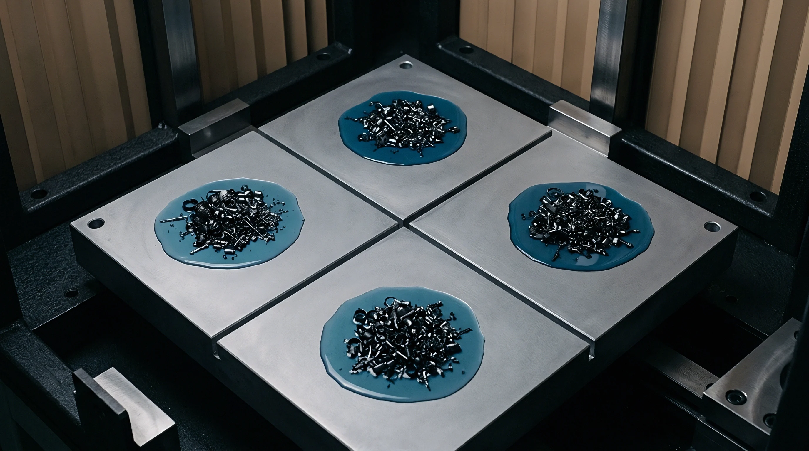
Numerical models tracking void formation implement dynamic boundary interface tracking or phase-field methods to alter the mesh as voids open. Once a microscopic void nucleates, the inner void surfaces form traction-free boundaries where normal components of electrical current, heat flux, and atomic flux vanish entirely. Current deflects around the void perimeter, generating an even more severe current crowding zone at the void tips.
The resulting local current density surge accelerates Joule heating, amplifying the localized thermal gradient and driving runaway void expansion across the under-bump contact interface until electrical open-circuit failure occurs.
A supplier who provides reliability models using isotropic bulk tin properties will obscure this risk. When qualifying packaging lines across southern manufacturing corridors, examining microbump electron backscatter diffraction data reveals grain orientations that routinely fail single-bump reliability predictions.
Chamber

Reliability Testing Specifications and Sample Architectures
Accelerated life testing of high-density flip chip packages requires precise control of ambient thermal profiles, bias current circuits, and continuous parametric data acquisition. The engineering standard JESD22-A154 governs electromigration testing of packaging interconnects, specifying constant current stress applied across dedicated test daisy-chain structures. Standard test conditions employ ambient convection oven chambers held between 125 and 150 degrees Celsius, coupled with constant electrical currents supplying average current densities between 5,000 and 15,000 amperes per square centimeter through each individual bump.
Kelvin bump structures are required to separate the bulk trace resistance of test boards from the milliohm-scale resistance shifts of the microbump interface. In a standard test coupon, four independent traces interface with each test bump: two force lines deliver the high direct current, while two sense lines monitor the voltage drop across the solder joint. High-speed multi-channel digital acquisition systems record real-time resistance shifts with micro-ohm resolution.
Accelerated test failure criteria typically trigger upon a 10 percent or 20 percent increase in initial baseline resistance, though early stage vacancy coalescence can alter the temperature coefficient of resistance long before bulk resistance shifts register on standard data logs.
A resistance shift exceeding twenty percent on a Kelvin sense loop marks terminal void coalescence across the under-bump metallization footprint.

How Does Asymmetric Temperature Offset Impact Interconnect Reliability?
In operating multichip modules and high-power packages, the silicon chip operates at significantly higher temperatures than the surrounding organic substrate, establishing an active cross-bump thermal gradient even without external ambient heating. When high direct current passes through microbumps under these conditions, the degradation rate depends heavily on whether electron flow runs from the hot silicon side to the cold substrate side or in reverse. The asymmetry arises because electromigration atomic flux and thermomigration atomic flux can either align in the same direction or directly oppose each other.
If the cathode sits on the die side, current flows downward from the chip to the substrate. Electrons travel from the hot chip toward the cooler substrate, matching the thermal gradient direction. Atomic flux from electromigration points downward.
Atomic flux from thermomigration points downward. The two forces combine additively, driving solder atoms rapidly toward the substrate side and generating extreme vacancy accumulation along the die interface. Conversely, when the cathode sits on the substrate side, electrons push atoms toward the hot die, directly opposing the downward thermomigration flux driven by thermal gradients.
This mechanical balance slows void growth substantially, creating orders-of-magnitude lifetime variations across alternating bump lines within the same package array.
Under-bump metallization structures mitigate these degradation pathways through diffusion barriers. Typical metallization stacks include electroless nickel immersion gold (ENIG), electroless nickel electroless palladium immersion gold (ENEPIG), and direct electroplated copper pillars capped with nickel and tin-silver solder caps. In copper pillar architectures, the copper pillar acts as a thermal heat sink, drawing heat away from the solder joint and blunting the localized current crowding hotspot.
However, intermetallic growth at the solder interface rapidly consumes available copper to form brittle Cu6Sn5 and Cu3Sn layers. The volume shrinkage associated with phase transformation from metallic copper and tin into intermetallic crystal lattices produces significant local tensile stresses, creating micro-voids known as Kirkendall voids along the copper-intermetallic boundary.
Packaging failure analyses consistently identify this intermetallic interface as the weakest mechanical link. When cyclic thermal fatigue combines with constant operational bias current, crack propagation tracks directly through the Kirkendall void band, bypassing bulk solder creep entirely. Suppliers asserting clean solder joints often skip long-dwell intermetallic thickness characterization, leaving assemblies vulnerable to unexpected operational failure.

Audit

Workshop Solder Integrity Verification
Factory audits assessing high-density packaging reliability require strict inspection routines centered directly on metallization chemistry, underfill dispensing, and reflow oven thermal uniformity. An auditor examining lines in Jiangsu or Guangdong packaging hubs reviews tool data logs rather than high-level process documentation. The inspection sequence moves systematically from raw wafer bumping to final underfill acoustic analysis.
- Plating bath chemistry must maintain copper and nickel contaminant thresholds below 5 parts per million to prevent non-equilibrium intermetallic segregation.
- Reflow thermal profiles require ten-zone conveyor tracking where peak dwell times between 240 and 250 degrees Celsius do not deviate by more than 1.5 degrees across the carrier width.
- Flux residue removal utilizes automated centrifugal inline deionized water cleaning at 65 degrees Celsius with surface resistivity verification exceeding 18 megaohm-centimeters.
- Underfill fillet heights require non-destructive optical gaging to ensure meniscus coverage reaches 75 to 90 percent of the silicon die edge thickness.
Micro-void distributions within the solder matrix demand non-destructive scanning acoustic microscopy (C-SAM) operating at transducer frequencies between 230 and 300 megahertz. Acoustic reflection modes at these frequencies detect delamination gaps between the underfill and the silicon passivation layer down to sub-micron thicknesses. When underfill separates from the die edge, mechanical triaxial confinement collapses immediately.
The loss of lateral constraint enables rapid atomic migration and solder extrusion under electromigration bias, terminating package operational life prematurely.
Destructive physical analysis supplements acoustic imaging. Metallographic cross-sectioning paired with field emission scanning electron microscopy (FE-SEM) examines the planar thickness of intermetallic compounds. At least twenty random microbumps per production lot require cross-sectioning and polishing using argon ion milling rather than purely mechanical diamond polishing.
Mechanical polishing introduces surface smearing that masks interfacial micro-cracking and intermetallic micro-voids. Electron backscatter diffraction mapping is performed on selected cross-sections to verify that tin grain structures do not exhibit single-crystal orientation aligned critically along the current flow vector.
Auditors verify automated optical inspection threshold parameters to prevent operators from widening machine acceptance windows during yield ramps. A common supplier compromise involves increasing conveyor speed through underfill dispense dispensing systems to relieve line bottlenecks. Shorter dwell times prevent capillary flow from clearing gas pockets beneath center-array microbumps, producing voids that alter package-wide mechanical compliance.
The audit protocol mandates inspection of real-time dispensing scale logs, cross-referencing fluid mass consumption against actual run counts per shift.


Ledger

Worked Engineering Assessment and Financial Quantification
Quantifying the financial liability of interconnect degradation requires modeling physical wearout kinetics against high-reliability mission profiles. Standard life prediction relies on Black’s equation modified to incorporate stress and thermal gradient acceleration factors:
MTTF = A_0 (J_e)^(-n) exp((E_a – Omega sigma_h) / (k T)) (1 + beta_TM grad(T))^(-1)
In this relationship, MTTF represents mean time to failure, A_0 is a geometric structural scaling constant, J_e is current density, n is current density acceleration exponent, E_a is diffusion activation energy, and beta_TM is the thermomigration coupling coefficient. Evaluating a high-density graphics processor bump array under severe workload demonstrates the impact of neglecting stress and thermal coupling.
Take an enterprise package with 4,500 active microbumps operating at an average bump current density of 8,500 amperes per square centimeter and an operating junction temperature of 105 degrees Celsius (378 Kelvin). Assume a baseline activation energy of 0.82 electron-volts, an atomic volume of 2.7 x 10^-29 cubic meters, and a current acceleration exponent of 1.8. Under stress-free, isothermal modeling assumptions, the predicted MTTF yields 115,000 continuous operating hours.
However, finite element multi-physics evaluation demonstrates that current crowding at the outer die edge bumps elevates local current density to 24,000 amperes per square centimeter, generating an internal thermal gradient of 1,450 degrees Celsius per centimeter and a localized tensile hydrostatic stress concentration of 45 Megapascals at the under-bump intermetallic corner.
Inserting these coupled values into the modified equation reduces the physical activation barrier from 0.82 electron-volts to 0.74 electron-volts due to the positive hydrostatic tension term. Coupled thermomigration accelerates voiding by an additional factor of 2.1. The recalculated MTTF plummets from 115,000 hours to 18,200 hours.
For an enterprise deployment intended for five years of continuous operation (43,800 hours), the package shifts from zero field defects during the warrantied period to systemic early field wearout beginning in month twenty-five.
| Cost Driver Parameter | Uncoupled Empirical Design | Fully Coupled Multiphysics Verification |
|---|---|---|
| Initial Design and Characterization Cost (USD) | $85,000 | $240,000 |
| Wafer Foundry Under-Bump Re-Masking Cost (USD) | $0 | $160,000 |
| Field Failure Rate Within 36 Months (%) | 4.2% | 0.08% |
| Expected Warranty Unit Returns (Units) | 21,000 | 400 |
| Field Replacement and Logistics Cost per Unit (USD) | $350 | $350 |
| Total Warranty and Field Replacement Liability (USD) | $7,350,000 | $140,000 |
| Net Financial Exposure (USD) | $7,435,000 | $540,000 |
The financial ledger proves that spending capital on coupled multi-physics modeling and aggressive metallization qualification saves millions in field liability. The primary expense of uncoupled modeling lies not in development engineering, but in warranty replacement campaigns, reverse logistics, and catastrophic brand erosion when systems fail in customer data racks. Factoring in secondary system losses, board rework rates, and client penalty clauses, front-loaded physical modeling represents the lowest-cost insurance policy available in semiconductor packaging operations.
When engineering teams omit hydrostatic and thermal coupling terms from bump lifetime models, warranty reserve calculations fail to cover the field replacement curve that emerges two years into commercial deployment.