Early Warning Indicators for Automated Electronics Assembly Lines
Real-time SMT line telemetry tracking vacuum decay, optical fiducial drift, and paste volume prevents high-cost downstream rework escapes.


Drift
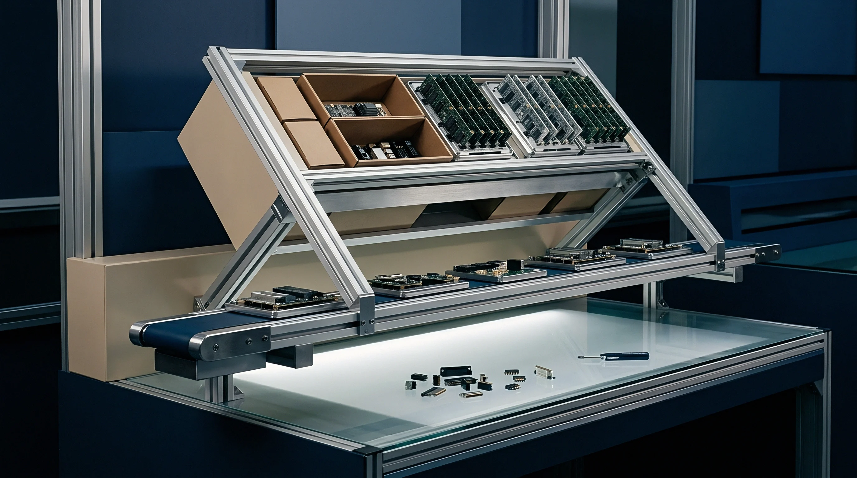
Placement systems often flag lateral board position errors well before post-reflow inspection ever logs a dropped component. Over a continuous ten-hour run, hydraulic pressure in the edge clamps drops enough for bare boards to slip up to eighty micrometers beneath high-speed placement heads. Corner fiducial cameras pull offsets for each panel, and if the mean offset across fifty consecutive circuit boards creeps steadily along one axis, the cause is usually mechanical wear in the slide guides or thermal expansion in the gantry frame.
Optical Fiducial Recognition Limits
Vision systems find target centers by matching pixel brightness against pre-loaded CAD files, but solder mask bleed, tarnished copper pads, and trace reflections gradually degrade contrast over long shifts. The camera LEDs also lose luminance after six months of steady use, cutting boundary contrast by as much as twelve percent. Once contrast drops below sixty-five percent, the software begins interpolating center points, which injects enough measurement noise to conceal actual mechanical drift.
Support pins set beneath the conveyor hold the board flat against nozzle downforce. If pin tips wear down or the pin layout is wrong, the center of the PCB sags under high-speed placement; as the nozzle lifts and the board snaps back, that vertical rebound turns into lateral bounce, nudging small passives right off their wet solder paste pads.
| Parameter | Baseline Value | Warning Level | Critical Failure Point |
|---|---|---|---|
| Fiducial X-Y Offset | ±10 micrometers | ±25 micrometers | ±45 micrometers |
| Target Brightness Contrast | 95 percent | 75 percent | 60 percent |
| Board Surface Deflection | 0.05 millimeters | 0.20 millimeters | 0.40 millimeters |
| Vision Calculation Latency | 4 milliseconds | 12 milliseconds | 25 milliseconds |
Conveyor Rail Parallelism
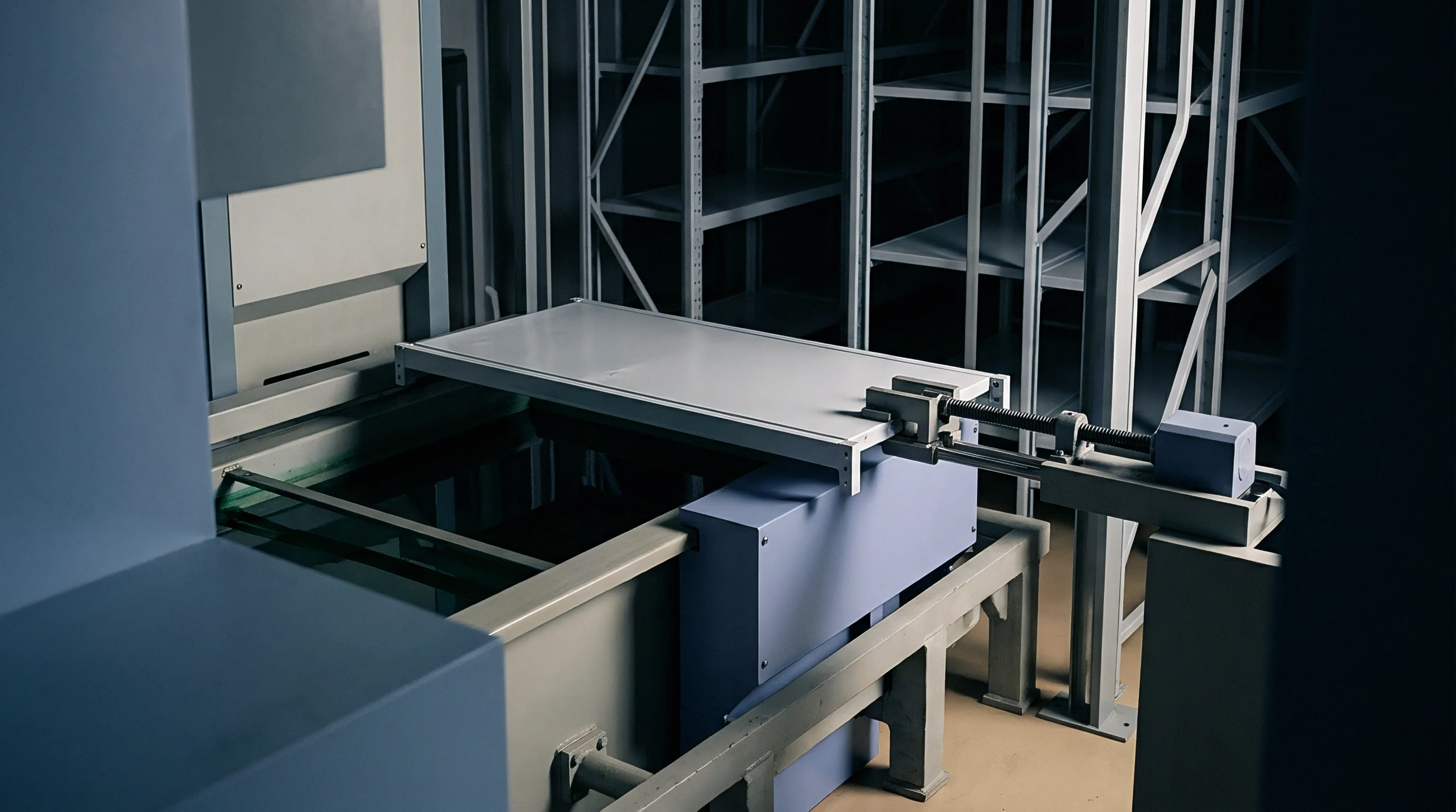
Lead-screw drives adjust rail width automatically between batch changes, but gearbox backlash can leave conveyor rails tapering up to 0.3 millimeters from entrance to exit. Boards running through non-parallel rails face uneven edge-clamping forces, twisting slightly along the conveyor centerline. When operators clear small transport jams by hand, they rarely recalibrate the mechanical edge stops afterward.
Systematic positioning errors show up on larger components long before smaller passives show trouble. Quad flat packages and other ICs with ninety-six or more perimeter leads readily take on rotational skew when clamping pressure is uneven, while worn upstream edge guides dump belt drive vibration straight into the panel during placement.
Without continuous automated optical inspection logging, plants tend to blame early misalignment on raw board variations rather than mechanical wear in the conveyor.

Nozzle
Reliable component picks require stable vacuum profiles inside the placement head. If plant air filters run past their service intervals, oil mist and moisture settle into the pneumatic manifolds, slowing response. Pick-head sensors track that vacuum drawdown to verify a clean part hold within fifteen milliseconds of contact.
Vacuum Decay Dynamics
Particulates from dirty air scour the internal cylinder walls, creating small leaks that show up under hard acceleration. When the gantry pulls turns exceeding three gravity units, vacuum drops below retention thresholds, letting parts skate across rubber or ceramic tip faces and skewing their orientation before the bottom camera ever reads them.
Vacuum differential drops below 18 kilopascals during high-speed placement trigger miss-picks on 0402 ceramic passives.
Wear on nozzle faces ruins the seal on molded plastic packages. For textured ceramic components, even minor tip erosion breaks the vacuum seal as the gantry whips across the chassis.
- Vacuum Pressure Loss follows debris buildup in pneumatic valves, dropping part retention during rapid gantry moves across the rail.
- Feeder Pitch Backlash develops as tape drive gears wear, presenting parts off-center from the pick nozzle.
- Tip Contamination builds from solder paste and tape adhesive sticking to the nozzle face, throwing parts out of square upon placement.
- Optical Mirror Occlusion tricks vision cameras into misreading component outlines, applying incorrect rotational offsets to square packages.
Feeder Mechanism Wear
Tape feeders step carrier tapes forward with ratchet cycles synced to the placement head. After roughly two million component tape pockets, sprocket teeth wear down enough to vary the stop position, leaving parts sitting four-hundredths of a millimeter behind nominal coordinates when the nozzle comes down.
An off-center pick exerts uneven downward pressure when the nozzle presses the lead into printed solder paste. Paste squashes out past the pad perimeter, forming hidden solder balls beneath the package body during reflow.
Replacing worn feeder hardware and nozzles with fresh tooling from maintenance storage clears these pick errors immediately.

Profile
Forced-convection reflow ovens heat panels across several sequential zones, but clogged baffles, tired blower motors, and aging heating elements degrade local convective transfer inside the tunnel. While zone thermocouples still register correct setpoint temperatures, they miss drops in the actual velocity of the circulating nitrogen gas.

Can Reflow Zone Thermocouples Detect Heater Degradation?
Stationary thermocouples mounted near heater coils still read target temperatures even as weak airflow starves the board of heat. Surrounding coils compensate by pulling additional current to hold the air temperature steady, which makes tracking current draw on individual heater banks the most reliable way to catch rising resistance before an alarm trips.
IPC-AJ-820A compliance guidelines specify that uncalibrated thermal zones cancel factory warranty obligations for voiding defects in ball grid arrays.
Bulky components absorb heat much slower than adjacent passives, driving steep thermal gradients across tight layouts. A drop of just ten-degree Celsius in peak reflow heat can leave paste unmelted under a central ball grid array array even while surrounding passives reach full liquidus, producing cold joints that crack during post-assembly vibration tests.
- Position calibrated probe sets across six heat zones.
- Run three consecutive test boards carrying embedded thermocouples.
- Record thermal delta profiles at ten-second intervals.
- Compare zone gradient slopes against original profile baselines.

Conveyor Speed Stability
Pin-chain conveyors pull loaded circuit boards through the tunnel at set rates measured in millimeters per minute. As drive bearings degrade from constant heat, conveyor speed stutters; boards that surge through peak zones spend too little time above liquidus, compromising intermetallic growth at the pad interface.
Stretched drive chains add mechanical slop, jerking the boards as the links seat into output sprockets. Any vibration while solder is molten causes passives to tombstone and bridges to form between tight connector pins.
Supply contracts typically mandate running thermal profiles with dedicated test vehicles at the start of every shift.

Slump
Solder paste rheology shifts as soon as it meets shop humidity and squeegee shear. Inline inspection systems check every pad for height, volume, and area before placement begins, but shearing paste across four hundred print cycles without replenishing solvent lowers viscosity significantly.

Rheological Degradation Metrics
When viscosity drops, printed brick profiles sag past pad margins before parts ever land. Cold slump develops while boards wait on buffer conveyors; hot slump takes over during the oven pre-heat ramp. If sagging paste spans fifty-percent of the spacing between 0.5-millimeter pitch leads, a hard electrical short forms at reflow.
| Inspection Parameter | Target Range | Action Limit | Line Action Trigger |
|---|---|---|---|
| Deposit Height Deviation | 100 ± 15 percent | 80 to 125 percent | Automated Stencil Clean |
| Solder Volume Index | 90 to 110 percent | 70 to 130 percent | Paste Replenishment Warning |
| Area Coverage Ratio | 98 to 102 percent | 90 to 105 percent | Squeegee Pressure Adjustment |
| Bridge Risk Index | 0 percent | > 2 percent area | Immediate Line Hold |
Using worn wiper blades or incorrect solvent mixtures leaves dried flux and tiny alloy balls caked along aperture walls. Clogged aperture corners choke paste volume on fine-pitch pads, creating open joints that get flagged downstream at post-reflow inspection.
Solder paste remaining on an idle stencil past ambient exposure limits causes bridging before visual bridging becomes apparent on finished boards.
- Aperture Inspection Gate compares average deposit volumes against CAD stencil dimensions every five panels.
- Paste Rheology Threshold flags viscosity loss when printed paste spreads fifteen percent beyond nominal aperture dimensions.
- Squeegee Pressure Audit tracks downward blade load to keep squeegees from scooping paste out of wide apertures.
- Stencil Clean Trigger runs automated vacuum wipes whenever panel deposit height variation exceeds twelve percent.

Ambient Environment Drift
Shifts in room temperature reshape the paste’s thixotropic behavior over an eight-hour run. If the floor climbs above twenty-six degrees Celsius, solvent evaporates rapidly and tackiness drops; nozzles cannot release components cleanly into dry paste, dragging parts off target centers during retraction.
If humidity drops below thirty percent, water-soluble pastes dry out so fast that component leads cannot penetrate the deposit cleanly during high-speed placement.
Skipping continuous solder paste volume monitoring trades upstream inspection time for expensive manual rework and customer field returns.

Takt
Keeping a line balanced requires steady takt times through printing, placement, reflow, and automated optical inspection. When station cycles drift out of sync, boards back up on transfer conveyors where exposed paste dries in shop air, while minor false-alarm stops at optical inspection compound the delay on dense multilayer panels.

Inspection Machine Overrides
Automated optical inspection units use neural networks and color-spectrum analysis to verify wetting angles. When false-call rates climb, operators have to review up to forty flagged defects per minute on line monitors; fatigue sets in quickly, and operators click past real voids and misaligned parts until defects escape into functional test.
| Shift Hour | Line Speed (Boards/Hr) | AOI False Call Rate | Manual Overrides/Hr | Escaped Defect Rate |
|---|---|---|---|---|
| Hour 1 to 2 | 120 | 1.2 percent | 18 | 0.001 percent |
| Hour 3 to 4 | 122 | 2.4 percent | 38 | 0.005 percent |
| Hour 5 to 6 | 118 | 4.1 percent | 62 | 0.022 percent |
| Hour 7 to 8 | 125 | 6.8 percent | 95 | 0.085 percent |
Connecting conveyor belts vibrate whenever boards accelerate between machines. If belt tension is loose, boards bounce against stops, dislodging unbaked components held only by paste surface tension.
False alarms at automated optical inspection stations prompt operator overrides that let actual component misalignments enter the reflow tunnel.
Line balancing software rarely reassigns placement heads fast enough to prevent queueing during unplanned reel changes, so supervisors track transit times between printers and placers to ensure paste open time stays under fifteen total minutes.

Margin
Yield economics on electronics lines turn almost entirely on how early defects are caught. Catching a solder bridge at the solder paste inspection station costs nothing in scrapped silicon, requiring only a thirty-second stencil wipe that costs less than twelve cents per panel.

Rework Cost Progression
Take a run of ten thousand main controller boards carrying five hundred components each. When insufficient paste volume under a ball grid array slips past inspection, the open joint is only discovered during final functional test, where troubleshooting demands X-ray analysis, board desoldering, pad redressing, and a fresh component.
Factor in technician hours, scrapped components, and X-ray machine time, and rework runs $14.80 per board at functional test. An escape rate of two percent on that ten-thousand-unit run adds $2,960 in direct floor rework; if bad boards slip past testing into customer devices, warranty claims, service calls, and shipping push costs to $210 per unit.
Deploying inline telemetry, automated paste monitoring, and scheduled nozzle maintenance requires about $28,000 in upfront tooling per line. Preventing twelve board escapes per thousand units covers the retrofit costs within five months of deployment.
Monitoring costs are easily outweighed by the scrap tallies, dead components, and emergency air-freight fees that pile up when quarantined shipments force rushed replacement runs.