Selecting Low Volume Silicone Molds for Plastic Parts
Select addition-cure platinum silicone molds and scale master patterns by 0.5-0.7% to maintain ±0.20mm tolerances across 20-shot casting runs.

Master

SLA and CNC Substrate Dynamics
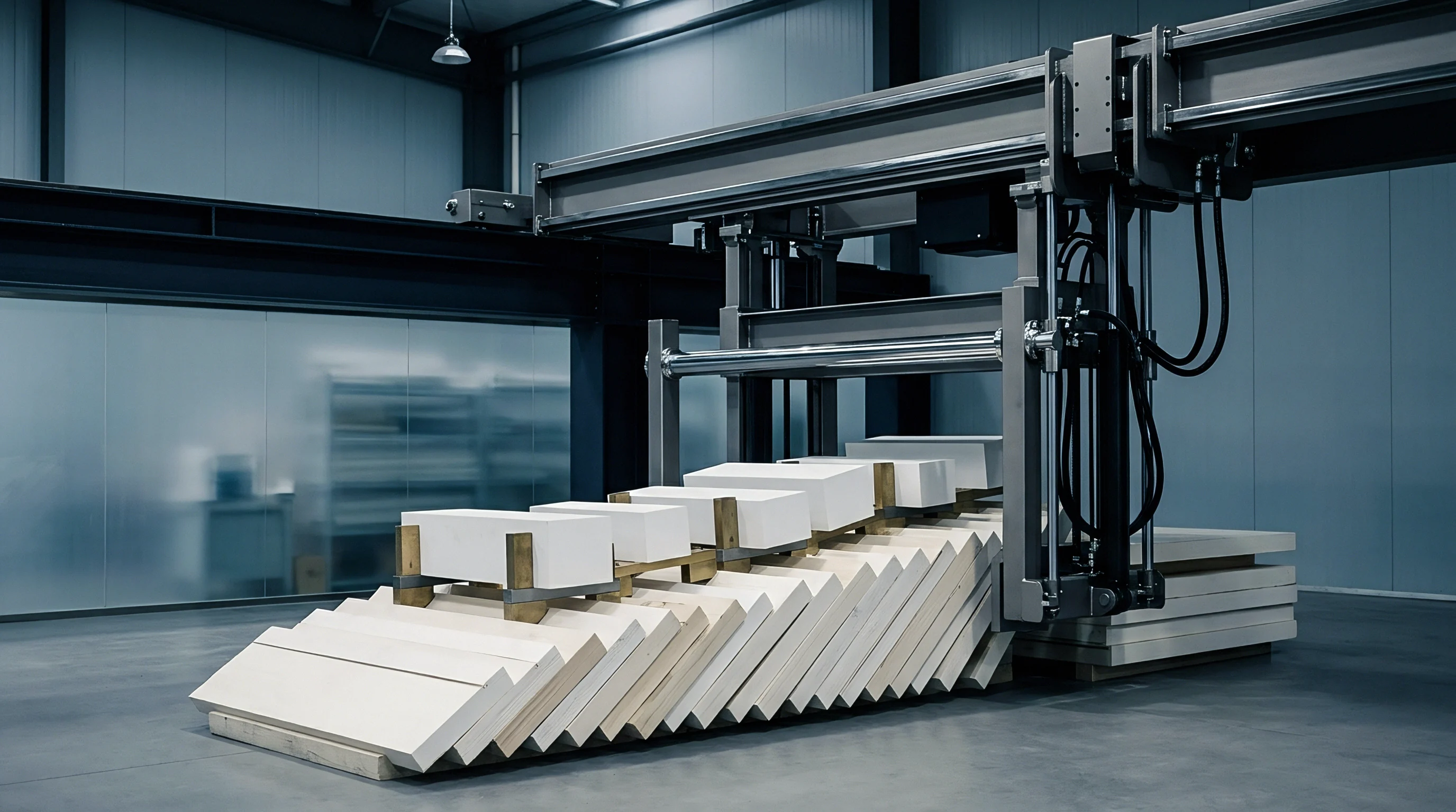
Master patterns set baseline geometry. The initial physical model defines every contour, texturing detail, and tolerance limit that the flexible silicone mold subsequently replicates. Selecting between stereolithography printing and high-speed CNC machining for the master pattern dictates the ultimate surface resolution and mechanical fidelity of the cast polyurethane parts.
High-resolution stereolithography using somatosensory epoxy resins achieves layer thickness down to 0.025 millimeters. Unprocessed additive surfaces retain microscopic stair-stepping along curved radii. These physical ridges create mechanical interlocks with the curing silicone liquid, generating high shear stresses during part demolding that tear the flexible cavity walls prematurely.
Machined aluminum or acrylic master patterns eliminate layer boundary artifacts entirely. High-speed CNC finishing operations using spherical ball-end cutters leave micro-milling tracks that require hand polishing to achieve optical clarity or high-gloss cosmetic textures. When selecting an acrylic master, solvent-polishing with vaporized dichloromethane smooths tool marks without rounding critical geometric edges.
Surface roughing distorts mold release. If the master pattern carries undercut features, the pattern draft angle must exceed 1.5 degrees per side to allow clean extraction from the surrounding liquid silicone block before curing completes.

Thermal Compensation and Multi-Stage Shrinkage
Plastic part dimensions undergo consecutive volumetric contractions throughout the silicone vacuum casting sequence. The master pattern must be oversized during initial CAD model generation to offset two distinct material shrinkage phenomena. First, the two-part liquid room-temperature vulcanizing silicone shrinks during its liquid-to-solid cross-linking phase.
Second, the polyurethane casting resin contracts as it polymerizes inside the preheated mold cavity.
Calculating the master pattern sizing vector requires compounding both volumetric expansion coefficients into a unified scale factor. Standard platinum-cure addition silicone exhibits a linear thermal and volumetric shrinkage factor between 0.1 percent and 0.2 percent. Typical polyurethane resins (simulating polypropylene, ABS, or polycarbonate) contract by 0.3 percent to 0.8 percent upon cooling.
Scaling the master pattern by a linear 0.5 percent to 0.7 percent compensates for this compound shrinkage across standard part geometries under 200 millimeters in length.
Surface Finishing and Parting Line Preparation
Applying surface sealants and release coatings onto the master pattern fixes the boundary state between the substrate and the liquid silicone mixture. Absorbent master materials such as porous SLA photopolymers or wood-filled composites require polyurethane primer sealing before pouring silicone. Unsealed photopolymer resins leak residual unreacted photoinitiators into the mold cavity, poisoning the silicone catalyst and leaving a soft, uncured gummy layer along the mold interior.
Establishing the parting plane requires mounting the master pattern inside a rigid acrylic or plywood casting box using non-sulfur modeling clay. Sulfur compounds within standard oil-based clays instantly inhibit the platinum complex catalyst in addition-cure silicone rubbers. Technicians position brass dowel pins along the clay parting line to mold mechanical location keys directly into the silicone block halves.
These keys prevent rotational shear and lateral registration slippage when the split silicone halves are clamped together during subsequent resin injection cycles.
Miscalculating the master pattern draft angle or using sulfur-tainted parting clay locks the master pattern inside a partially cured silicone block, destroying both the tooling substrate and fifty kilograms of raw compound in a single shop cycle.

Silicone

Addition Cure versus Condensation Chemistry
Liquid silicone choices for room-temperature vulcanizing vacuum casting molds fall into two distinct chemical classifications: organotin-catalyzed condensation cure formulations and platinum-catalyzed addition cure formulations. Condensation-cure silicones utilize tin octoate or dibutyltin dilaurate to drive hydroxyl-terminated polydimethylsiloxane condensation. This reaction releases alcohol vapor as a volatile byproduct.
The evaporation of this volatile component produces significant long-term linear shrinkage ranging from 0.4 percent to 0.8 percent over thirty days, causing gradual mold warping and dimensional instability in stored tooling.
Platinum silicone minimizes volumetric shrinkage. Addition-cure formulations involve vinyl-functional polysiloxanes reacting with hydride-functional siloxanes in the presence of a soluble platinum catalyst complex. The chemical reaction generates no volatile byproducts, resulting in post-cure linear shrinkage consistently below 0.05 percent over extended storage periods.
Platinum-cure formulations offer high tear strength ranging from 25 to 35 Kilonewtons per meter and shore hardness options between 30 Shore A and 40 Shore A, providing the elastic elasticity required to flex over deep geometric undercuts without permanent structural tearing.
Platinum-cure addition silicones sustain linear post-cure shrinkage below 0.05 percent over 30 days when maintained at 22 degrees Celsius and 50 percent ambient humidity.

Degassing Cycles and Viscosity Control
Achieving defect-free silicone molds requires total elimination of entrained air bubbles introduced during two-part mechanical mixing. Mixed room-temperature vulcanizing silicone exhibits an initial viscosity between 30,000 and 60,000 millipascal-seconds, creating significant pneumatic resistance to natural bubble ascension. Technicians place the blended liquid compound inside a sealed vacuum chamber operating at negative atmospheric pressures reaching -0.098 Megapascals.
Vacuum pressure removes trapped pockets. Under deep vacuum, entrained air bubbles expand up to thirty times their original volume, causing the liquid silicone level to rise dramatically inside the mixing container. The operator must cyclically break vacuum pressure two to three times during the degassing window to collapse the foam head before the liquid overflows.
The entire degassing phase must finish within 25 percent of the working pot life, which typically spans 40 to 60 minutes for standard 30 Shore A platinum formulations at 25 degrees Celsius.
| Chemical Base | Catalyst Type | Mixed Viscosity (mPa·s) | Shore Hardness | Tear Strength (kN/m) | Linear Shrinkage (%) |
|---|---|---|---|---|---|
| Polydimethylsiloxane | Tin Octoate (Condensation) | 28,000 – 35,000 | 25 Shore A | 18 – 22 | 0.40 – 0.75 |
| Vinyl Polysiloxane | Platinum Complex (Addition) | 40,000 – 55,000 | 30 Shore A | 28 – 32 | 0.02 – 0.08 |
| High-Tear Vinyl Polymer | Platinum Complex (Addition) | 50,000 – 65,000 | 40 Shore A | 35 – 42 | 0.01 – 0.05 |
When parts show severe surface voids along rib structures, regional tooling suppliers frequently claim the master pattern geometry possessed hidden air traps that no vacuum cycle could draw out during the pour.
Exotherm

Polyurethane Resin Exotherm and Mold Attack
Thermoset polyurethane casting resins release significant exothermic heat energy as chemical polymerization crosses functional groups. Liquid polyurethane components consisting of polyols, isocyanates, and chain extenders are preheated to 35 degrees Celsius before mixing inside a vacuum chamber. Once injected into the cured silicone cavity, the cross-linking reaction accelerates, generating peak internal cavity temperatures reaching 80 to 110 degrees Celsius depending on part wall thickness.
Exotherm heat degrades mold cavities. Thick plastic features exceeding six millimeters concentrate thermal mass, creating localized hot spots along the silicone wall. This repeated thermal spiking accelerates chemical degradation of the silicone polymer network.
Thermal stress severs methyl side groups from the siloxane backbone, turning the once-flexible silicone cavity brittle, hard, and chalky along high-temperature zones.

Shot Life Decay and Silicone Oil Leaching
Silicone oil bleeds under heat. Standard RTV silicone rubbers contain unbonded silicone fluid additives designed to lower viscosity and adjust Shore A hardness. Under repeated exposure to exothermic polyurethane cure cycles and aggressive resin solvents, this silicone oil migrates to the cavity surface and leaches into the cast plastic parts.
Mold walls soften after twenty shots. As silicone fluid bleeds out of the tool, the cavity surface loses its elastic compliance and surface slip characteristics. Polyurethane resin begins chemically bonding directly to the exposed siloxane chains.
Surface finish quality degrades progressively across successive casting operations. Cosmetic parts transition from high-gloss clarity on early shots to a pitted, hazy matte appearance as surface micro-tears multiply across the silicone boundary.
Standard ISO 8528 thermal cycling protocols confirm that cavity temperature spikes above 95 degrees Celsius reduce platinum silicone tooling life by 40 percent per additional 10 degrees rise.
Degraded silicone molds display specific physical and geometric failure modes during low-volume vacuum casting operations:
- Cavity Micro-Tearing appears as fine, jagged web patterns along sharp internal corners where the brittle silicone elastomer failed during manual part extraction.
- Dimensional Wall Bowing manifests when thin perimeter mold walls lose structural rigidity due to thermal breakdown, expanding outward under liquid resin head pressure.
- Surface Gloss Hazing occurs when silicone oil depletes from the cavity interface, causing cast parts to stick and pull microscopic silicone flakes away from the wall.
- Parting Line Erosion develops along mold split lines where repeated scraping with brass flash-removal spatulas chips away soft silicone sealing lips.
How much thermal insulation buffer can be engineered into a two-part silicone mold structure before cavity thermal expansion distorts critical wall thicknesses beyond print specifications?

Tolerances

What Tolerance Limits Apply to Vacuum Cast Parts?
Vacuum cast polyurethane parts cannot achieve the strict linear tolerances of precision steel injection tooling. Achieving tight tolerances requires accounting for three distinct error vectors: master pattern manufacturing variance, flexible silicone cavity deformation under hydraulic head pressure, and thermoset polyurethane chemical shrinkage during thermal curing. Standard production capability matrices for vacuum cast plastic parts establish baseline limits across specific dimension ranges.
Polyurethane shrinks during cure cycles. For features under 100 millimeters, achievable tolerances maintain a baseline band of ±0.20 millimeters. For linear dimensions between 100 millimeters and 500 millimeters, tolerance bands scale at ±0.25 percent of the nominal length.
Critical alignment features, such as press-fit bearing seats or PCB mounting bosses, require metal thread inserts or post-cast CNC machining operations to hold tolerances tighter than ±0.08 millimeters.
| Nominal Dimension Range (mm) | Rigid ABS-Like PU (mm) | Polycarbonate-Like PU (mm) | Elastomeric Rubber PU (mm) |
|---|---|---|---|
| 0.1 – 50.0 | ±0.15 | ±0.18 | ±0.35 |
| 50.1 – 150.0 | ±0.25 | ±0.30 | ±0.50 |
| 150.1 – 300.0 | ±0.40 | ±0.45 | ±0.85 |
| 300.1 – 600.0 | ±0.65 | ±0.75 | ±1.25 |

Structural Elasticity and Clamp Pressure Variations
Clamping force shifts parting lines. Silicone molds lack rigid mechanical core-and-cavity locks. Technicians secure the two halves of a split silicone block using heavy rubber bands, wooden pressure plates, or manually tightened ratcheting cargo straps.
Applying uneven clamping pressure deforms the flexible elastomeric cavity, altering internal cross-sectional wall thicknesses and generating uneven flash along parting lines.
Hydraulic head pressure during vacuum resin filling exerts outward force against internal cavity walls. Deep parts with wide flat spans experience outward wall bulging if the surrounding silicone mass is under three centimeters thick. Maintaining minimum mold wall proportions relative to part dimensions provides the mechanical resistance needed to hold flat surfaces within acceptable planarity parameters.
According to DIN 16742 plastic mold tolerance classification TG7, flexible tooling materials require an expanded tolerance envelope of ±0.30 mm for features up to 100 mm.
A rigorous mold receiving and first-article verification procedure prevents out-of-tolerance parts from entering assembly workflows:
- Measure master pattern dimensions using a calibrated coordinate measuring machine prior to silicone encasement.
- Verify master pattern surface roughness metrics across all cosmetic zones using a contact profilometer.
- Perform a durometer hardness check on the cured silicone block to ensure complete platinum catalyst reaction across the core thickness.
- Inspect first-shot cast parts with optical CMM scanners to map volumetric dimensional deviation against native CAD models.
- Conduct cross-sectional wall thickness audits along cut part samples to verify internal core registration and clamp pressure consistency.
All supply contracts for low-volume plastic components specify that part acceptance relies strictly on dynamic CMM coordinate reports generated within 24 hours of demolding, measured at a controlled ambient baseline of 20 degrees Celsius and 45 percent relative humidity.


Economics

Unit Cost Crossover Arithmetic
Selecting silicone tooling over rapid aluminum or steel injection molds represents a balance between upfront capital expenditure and recurring piece-part amortizations. Silicone molds require minimal capital investment for master pattern production and silicone compound filling, but their limited operational lifespan of 15 to 25 shots per cavity elevates the per-unit labor and resin costs significantly.
Unit costs drop as quantities rise. Rapid steel costs more initially. Rapid aluminum tooling requires high initial NRE expenditure for CNC mold machining, core-side EDM spark erosion, and ejector pin plate fitting.
Aluminum tooling yields lower piece-part costs over production volumes spanning 1,000 to 10,000 units. Calculating the exact economic crossover point between silicone vacuum casting and rapid aluminum injection tooling determines the ideal tooling route for prototype-to-production transitions.
| Batch Quantity | Silicone Tooling Cost ($) | Silicone Unit Cost ($) | Rapid Aluminum NRE ($) | Aluminum Unit Cost ($) |
|---|---|---|---|---|
| 10 Parts | 450 | 42.00 | 4,800 | 8.50 |
| 50 Parts | 1,350 (3 molds) | 38.00 | 4,800 | 6.20 |
| 100 Parts | 2,700 (6 molds) | 36.00 | 4,800 | 4.80 |
| 500 Parts | 13,500 (30 molds) | 35.00 | 4,800 | 2.90 |

Worked Cost Comparison for Low Volume Enclosures
Silicone tooling serves short production runs. Consider a complex electronics enclosure measuring 180 mm by 120 mm by 45 mm, modeled in rigid ABS-like polyurethane. Producing a single high-resolution SLA master pattern with hand-sanded cosmetic finishing costs approximately $450.
A platinum-cure silicone mold block poured around this master requires six kilograms of liquid silicone at $35 per kilogram, yielding a baseline tooling cost of $660 for the first mold block.
Assume the silicone mold maintains cosmetic fidelity for 20 casting cycles before thermal degradation requires tool retirement. Producing 100 finished enclosures demands five consecutive silicone mold builds created from the original SLA master pattern. The cumulative silicone tooling cost totals $3,090, representing $450 for the master pattern plus $2,640 for five silicone mold recreations.
Individual polyurethane resin shots, vacuum chamber operator time, flash trimming, and post-cure baking add $36 in direct labor and material costs per part. The fully amortized cost per unit across 100 enclosure parts equals $66.90.
Compare this sequence against a single-cavity P20 rapid aluminum injection mold costing $5,200 in upfront NRE machining fees. With production injection molding processing real ABS resin at a unit price of $3.20, total expenditure for 100 enclosures equals $5,520, yielding an amortized unit cost of $55.20. At the 100-unit threshold, rapid aluminum tooling achieves absolute commercial parity with vacuum casting, while offering superior dimensional stability, shorter cycle times, and real production-grade thermopolymers.
Rapid aluminum injection tooling achieves direct landed cost parity with multi-mold silicone vacuum casting at approximately 80 to 110 units for medium-complexity plastic enclosures.
To ensure precision execution across low-volume manufacturing requests, every formal Request for Quotation sent to vacuum casting vendors includes clear parameters:
- Master Pattern Material specifies high-resolution SLA epoxies or CNC acrylics with explicit surface roughness targets below Ra 0.4 micrometers.
- Silicone Chemistry Type mandates addition-cure platinum formulations with tear strengths exceeding 30 Kilonewtons per meter.
- Guaranteed Cavity Lifespan defines the maximum allowed shot count per silicone mold before compulsory mold retirement and free-issue tool re-pouring.
- Resin Flame Rating demands specific UL 94-V0 thermoset polyurethane grades with attached material safety and thermal deflection test certificates.
Managing low-volume plastic production across international supply lines requires strict oversight of silicone chemistry, master pattern scaling arithmetic, and shot-life degradation schedules. Procurement teams that audit master pattern geometry and verify platinum-cure addition silicone specifications lock in repeatable part dimensions while maintaining full control over crossover timing for hard injection tooling transitions.