Interfacial Intermetallic Compound Kinetics in Lead Free Solder Joints
Control reflow peak dwell and solid-state thermal exposure to limit interfacial intermetallic growth below four micrometers, preventing brittle joint fracture.

Reaction
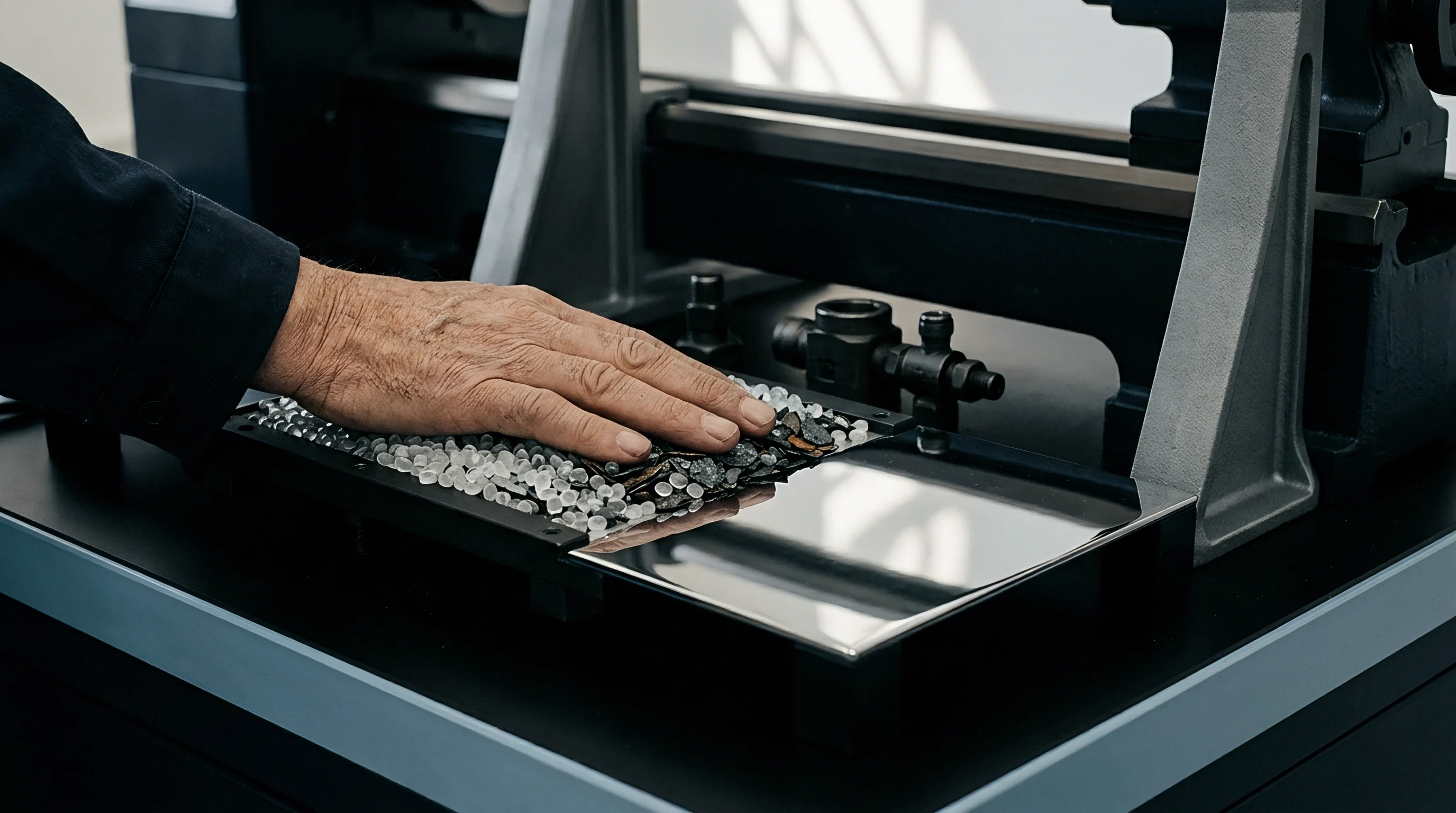
Molten lead-free alloys deposit intermetallic compounds the instant liquid tin contacts a copper or nickel substrate. Liquid SAC305 (96.5Sn-3.0Ag-0.5Cu) wetting bare copper dissolves the metal at rates exceeding 0.1 micrometers per second at 245 degrees Celsius, saturating the liquid boundary layer with copper atoms and nucleating scalloped eta-phase Cu6Sn5 crystals within three seconds.
Initial liquid-solid reactions govern all downstream metallurgical behavior. Joint cohesion relies on more than physical interlocking; chemical bonding forms a distinct crystalline interlayer between the bulk solder matrix and substrate metallization. This initial layer grows in uneven, hemispherical scallops, creating deep grooves that give liquid tin fast diffusion pathways until the solder freezes solid.
Peak reflow temperatures above 255 degrees Celsius accelerate copper dissolution beyond 0.18 micrometers per second.
Substrate composition dictates which crystal structure forms at the interface. Bare copper pads yield Cu6Sn5 during reflow, while nickel-based finishes yield Ni3Sn4 or mixed (Cu,Ni)6Sn5 ternary compounds. Silver in SAC alloys alters liquidus dynamics without forming primary silver-tin intermetallics directly on the substrate, though Ag3Sn plates do precipitate in the nearby bulk matrix.

Thermodynamic Driving Forces during Wetting
Chemical potential gradients across the liquid-solid interface supply the driving free energy for compound formation. Tin has a strong affinity for copper, yielding a standard Gibbs free energy change of roughly negative 5.8 kilojoules per mole for Cu6Sn5 formation at typical soldering temperatures.
Reflow dwell time at peak temperature dictates initial layer thickness. Extending the liquid dwell beyond ninety seconds increases scallop height from a baseline 1.2 micrometers to over 3.5 micrometers. These thick layers lock in thermal stresses during cooling because of the expansion mismatch between the intermetallic compound (18.4 ppm per degree Celsius) and the copper substrate (16.5 ppm per degree Celsius).

Diffusion
Solid-state atomic migration continues to drive intermetallic growth long after an assembly leaves the reflow oven. Operating heat fuels solid-state diffusion, turning the original scalloped layer into a continuous, planar band that thickens along a parabolic curve over time.
A standard one-dimensional growth model expresses total compound thickness through empirical kinetic equations:
W(t) = W_0 + (D t)^n
Here W(t) represents total thickness at time t, W_0 is the post-reflow thickness, D is the effective diffusion coefficient, and n is the time exponent. An n value near 0.5 confirms volume diffusion across the intermetallic layer, while values dropping toward 0.33 point to grain boundary diffusion through the intermetallic lattice.
| Substrate Interface | Intermetallic Layer | Activation Energy Q (kJ/mol) | Diffusion Constant D0 (m2/s) | Time Exponent (n) |
|---|---|---|---|---|
| Cu (Electrolytic) | Cu6Sn5 + Cu3Sn | 84.2 | 3.12 x 10^-6 | 0.48 |
| Cu (Rolled-Annealed) | Cu6Sn5 + Cu3Sn | 88.6 | 4.45 x 10^-6 | 0.46 |
| Electroless Ni-P | (Cu,Ni)6Sn5 + Ni3Sn4 | 102.5 | 1.85 x 10^-5 | 0.42 |
| Direct Electrolytic Ni | Ni3Sn4 | 118.3 | 7.20 x 10^-5 | 0.39 |

Sublayer Formation and Kirkendall Voiding
Extended thermal exposure causes phase separation at copper-tin interfaces. When temperatures stay above 100 degrees Celsius, a secondary epsilon-phase Cu3Sn sublayer nucleates between the original Cu6Sn5 layer and the underlying copper pad.
Differences in atomic diffusion rates create micro-voids in the structure. Copper atoms migrate into the Cu3Sn layer faster than tin diffuses toward the copper pad, creating a net vacancy flux toward the Cu/Cu3Sn interface. These vacancies eventually coalesce into micro-cavities known as Kirkendall voids.
IPC-7095 Class 3 criteria designate void area fractions above fifteen percent along the pad interface as critical structural defects.
Void density correlates strongly with electroplating impurities in the substrate. Residual sulfur, carbon, and organic brighteners from electrolytic copper baths concentrate at the Cu/Cu3Sn boundary during thermal aging, lowering the nucleation energy needed for Kirkendall voids to form.
- Interlayer thinning occurs as Cu6Sn5 breaks down to supply tin atoms to the expanding Cu3Sn phase boundary.
- Vacancy supersaturation concentrates along copper crystallographic planes containing high dislocation densities.
- Micro-crack propagation follows these planar void bands under cyclic thermal shock loading.
Elevated storage temperatures accelerate void coalescence. Assemblies held at 125 degrees Celsius for one thousand hours develop continuous void chains across seventy percent of the copper pad interface.


Barrier
Surface finishes protect circuit board copper from oxidation and slow interfacial diffusion. Options like Electroless Nickel Immersion Gold (ENIG), Electroless Nickel Electroless Palladium Immersion Gold (ENEPIG), and Organic Solderability Preservatives (OSP) each introduce distinct diffusion dynamics to the solder joint.
Electroless nickel deposits contain six to nine weight percent phosphorus. During soldering, tin reacts with nickel to form ternary (Cu,Ni)6Sn5 or binary Ni3Sn4 intermetallics. As nickel is consumed, expelled phosphorus concentrates at the boundary, forming a thin, phosphorus-rich Ni3P layer alongside a metastable Ni-Sn-P phase.
| Finish Architecture | Primary Formed IMC | Secondary Phase | Average Growth Rate (125C, nm/hr) | Brittleness Tendency |
|---|---|---|---|---|
| OSP on Bare Cu | Cu6Sn5 | Cu3Sn | 4.2 | Moderate (Driven by Kirkendall Voids) |
| ENIG (7-9% P) | (Cu,Ni)6Sn5 | Ni3P / Ni-Sn-P | 1.1 | High (Phosphorus segregation) |
| ENEPIG (Pd Barrier) | (Cu,Ni,Pd)6Sn5 | (Ni,Pd)3Sn4 | 0.8 | Low to Moderate |
| Immersion Silver | Cu6Sn5 | Cu3Sn | 3.9 | Moderate |

How Does Palladium Alter Nickel Dissolution?
The thin palladium layer in ENEPIG finishes dissolves into molten solder within the first two seconds of reflow. Once dissolved, palladium alters the surface energy of the liquid alloy and slows down dissolution of the underlying nickel barrier.
Incorporated palladium alters the lattice constant of the growing (Cu,Ni)6Sn5 layer, reducing atomic volume mismatch between the intermetallic crystals and the nickel pad. This lowers residual shear stress across grain boundaries. Palladium concentrations in the intermetallic layer typically stabilize between one and three atomic percent, suppressing the formation of brittle Ni3P bands.
Gold plating thickness on ENIG lines that drifts above 0.12 micrometers triggers gold embrittlement. Excess gold dissolves instantly into liquid solder during reflow and precipitates during cooling as brittle, quadrangular AuSn4 crystals right at the intermetallic interface.

Fracture
As joints age, mechanical failure shifts from ductile yielding within the bulk solder to brittle cleavage at the intermetallic boundary. Intermetallic compounds are hard and exhibit negligible plastic deformation compared to bulk tin-rich alloys.
Fracture toughness (K_IC) measures roughly 1.4 MPa m^0.5 for Cu6Sn5 and 1.2 MPa m^0.5 for Cu3Sn. By contrast, bulk SAC305 absorbs energy through dislocation glide under low strain rates. When impact or drop loads generate shock waves, the stiff intermetallic layer cannot yield, concentrating shear and tensile stresses directly at the phase boundaries.
Intermetallic thicknesses exceeding four micrometers drop ball-impact shear resistance by more than forty percent.
Brittle fracture paths track specific chemical interfaces depending on surface metallurgy and thermal history:
- Substrate separation follows the boundary between electroplated copper and Cu3Sn where Kirkendall voids congregate.
- Phase-boundary cleavage runs between the Cu3Sn sublayer and overlying Cu6Sn5 scallops under pure tensile loads.
- Phosphorus layer rupture occurs along black pad interfaces where hyper-corroded electroless nickel creates weak Ni3P planes.
- Inter-grain separation shears through thick Cu6Sn5 grain boundaries during high-speed drop impacts above five hundred gravities.
High-speed ball shear tests isolate these brittle failure modes using impact speeds between 1.0 and 4.0 meters per second. As-reflowed joints fail in a ductile manner through the bulk solder, leaving dimpled cup-and-cone fractures. After isothermal aging at 150 degrees Celsius for five hundred hours, failure shifts entirely to brittle interfacial cleavage across the entire pad footprint.
On a 0.4-millimeter pitch Ball Grid Array (BGA) package soldered to an OSP-finished board, initial reflow forms a 1.2-micrometer Cu6Sn5 layer. Operating at 85 degrees Celsius for five years thickens this intermetallic structure to 3.8 micrometers, building an underlying 1.1-micrometer Cu3Sn sublayer with twelve percent Kirkendall void coverage. Under JESD22-B111 drop testing, survival drops from twenty falls to just two.
Trace dopants alter these fracture paths. Adding 0.05 weight percent nickel or 0.01 weight percent cobalt to SAC solder alloys refines the intermetallic grain structure and suppresses planar Cu3Sn growth during aging.


Pad
Board layout rules directly influence thermal mass and local intermetallic growth rates. Non-Solder-Mask-Defined (NSMD) pads expose copper sidewalls, which increases wetting area and spreads mechanical stress across a larger perimeter than Solder-Mask-Defined (SMD) pads.
Mask encroachment on SMD pads introduces stress concentrations along the mask edge. As molten solder shrinks against the mask during cooling, micro-voids and irregular intermetallic scallops form right under the mask lip, creating a geometric notch where fatigue cracks initiate during vibration.

Thermal Profiling Constraints in Production
Reflow thermal profiles dictate the initial intermetallic growth. Process engineers must balance thorough flux activation and wetting against excessive time above liquidus (TAL).
- Time above liquidus window: maintain 45 to 75 seconds above 217 degrees Celsius for SAC305.
- Peak temperature dwell range: hold between 235 and 248 degrees Celsius across all thermal zones on the circuit board.
- Cooling gradient setting: enforce a cooling rate between 2.5 and 4.0 degrees Celsius per second to promote finely dispersed Ag3Sn precipitates.
Cooling slower than 1.5 degrees Celsius per second allows large Ag3Sn plates to grow in the bulk solder. These plates can extend into the interfacial zone, acting as stress raisers that route shear cracks directly into the brittle intermetallic layer.
Verifying intermetallic thickness on pre-production runs requires metallographic cross-sectioning and Scanning Electron Microscopy (SEM) with Energy Dispersive X-ray Spectroscopy (EDS). Standard optical inspection cannot resolve thin Cu3Sn sublayers or detect early Kirkendall voiding under Cu6Sn5 scallops.
Skipping thermal profiling across different PCB revisions leaves uneven copper distribution unmanaged. Variations in thermal mass distort peak temperatures, driving excessive intermetallic growth on low-density corner pads while high-density central BGA pads develop cold-joint wetting defects.