Electrolyte Fluid Shear Dynamics in Industrial Plating Line Operations
Optimizing electrolyte shear dynamics compresses boundary layers, enabling higher current densities while cutting drag-out loss and plating defect rates.

Velocity

Boundary Layer Mass Transport
Electrodeposition inside industrial plating tanks relies on the continuous transport of solvated metal ions across a stationary fluid film adjacent to the cathode surface. Dynamic fluid motion compresses this stagnant layer, decreasing diffusional distance and elevating the critical current density limit. Without sufficient momentum transferred from the bulk electrolyte, ion depletion occurs rapidly at high current densities, producing dendrites, powdery deposits, and localized burning.
Wall shear rate dictates the thickness of the Nernst diffusion layer. Higher shear rates flush depleted fluid away from the workpiece, maintaining a uniform concentration gradient across complex substrate geometries. In automated reel-to-reel and rack plating systems operating across Zhuhai and Ningbo industrial zones, bath flow rates are frequently dialed down by machine operators to limit chemical splash or mechanical movement off the rack.
This operational compromise expands the boundary layer, restricting maximum allowable current density by up to forty percent.
Plating lines operating at bath agitation velocities below 0.3 meters per second exhibit boundary layer thicknesses exceeding fifty micrometers, severely restricting cathode efficiency.
Reynolds numbers within industrial plating channels classify fluid dynamics into laminar, transitional, or turbulent regimes. Laminar flow creates predictable, parallel fluid streams that fail to penetrate narrow recesses, high-aspect-ratio printed circuit board microvias, or tight leadframe cavities. Turbulent flow disrupts boundary layers through chaotic eddy formation, enhancing mass transfer while introducing high wall shear stress variations across the part profile.

Shear Stress Distribution at the Cathode Surface
Shear stress experienced by the substrate surface varies as a function of fluid density, dynamic viscosity, and localized flow velocity gradient. Excessive shear stress strips organic additives, such as brighteners and suppressors, from target surfaces before adsorption completes. This stripping action alters polarization behavior, generating inconsistent plate thickness across raised features and recessed corners.
Non-uniform shear distribution causes uneven additive consumption across the cathode surface. Regions subjected to localized high-velocity fluid streams experience enhanced convective transport of organic levellers, which suppresses deposition rate relative to low-shear zones. Balancing localized velocity profiles prevents thickness variation across wide panels and complex three-dimensional stampings.
Failure to regulate fluid shear across cathode geometries yields unacceptably wide plating thickness standard deviations, forcing premature rejection during final quality control inspections.


Bath

Eductor Nozzle Configuration and Recirculation Geometry
Mechanical air sparging introduces dissolved oxygen, oxidizes delicate bath additives, and causes inconsistent solution movement. Modern high-speed plating lines replace compressed air agitation with submerged eductor nozzle arrays. Eductors leverage the Venturi principle, drawing five liters of surrounding tank solution into the primary plume for every single liter pumped through the nozzle orifice.
This volumetric multiplication generates controlled, high-velocity liquid streams across target plating zones without introducing atmospheric gases.
Positioning eductor manifolds requires precise alignment relative to rack movement vector and substrate orientation. Plume overlap must occur prior to contacting the workpiece surface to prevent localized high-velocity hot spots. When eductor vectors directly hit flat substrate faces perpendicular to flow, fluid stagnation points form at the impact centers, creating localized low-shear zones surrounded by high-shear rings.
Standard operating procedures for configuring submerged agitation arrays follow a strict mechanical sequence:
- Mount bottom-entry manifold piping using rigid polyvinylidene fluoride supports fixed to the inner tank frame.
- Space eductor nozzles at intervals equal to 1.5 times the standoff distance from the cathode plane.
- Angle nozzle discharges twenty-five degrees upward toward the liquid surface to induce secondary bulk tank circulation.
- Install magnetic-drive centrifugal pumps rated for minimum tank volume turnovers of eight to twelve changes per hour.
- Calibrate inline pressure gauges at the manifold inlet to maintain discharge pressure between 0.12 and 0.18 megapascals.
Fluid Transport inside Recessed Features
Reaching deep recesses, blind holes, and high-aspect-ratio microvias requires targeted fluid velocity vectors capable of overcoming surface tension resistance. Static fluid inside blind holes acts as a hydraulic barrier, blocking fresh ions from reaching hole bottoms. Impinging flow manifolds generate localized shear forces that force fluid exchange inside features down to 50-micrometer diameters.
| Agitation Method | Mean Wall Shear (Pa) | Diffusion Layer Thickness (μm) | Dissolved Oxygen (ppm) | Max Usable Current Density (A/dm²) |
|---|---|---|---|---|
| 0.15 – 0.45 | 35 – 50 | 6.5 – 8.2 | 2.5 – 3.5 | |
| 0.05 – 0.20 | 45 – 65 | 2.1 – 3.0 | 1.8 – 2.5 | |
| 0.80 – 2.50 | 10 – 20 | 1.2 – 1.8 | 6.0 – 10.0 | |
| 2.20 – 6.00 | 5 – 12 | 1.1 – 1.6 | 12.0 – 20.0 |
In impinging jet configurations, higher pump pressure generates micro-vortices at feature entrances. These micro-vortices strip stagnant bubbles and replenish metal salts inside deep features. Proper nozzle targeting ensures microvia center plating speeds match surface deposit rates, preventing void formation in printed circuit manufacturing.
Eductor manifolds angled parallel to cathode motion yield maximum diffusion boundary layer compression without creating physical distortion on delicate copper foil panels.


Defect
Shear-Induced Deposition Anomalies
Shear imbalance across industrial plating lines induces distinct physical defects on electroplated components. Under insufficient shear, hydrogen gas bubbles produced as side reactions during deposition cling to cathode surfaces. Trapped bubbles create hemisphere-shaped micro-pits, exposing substrate material to corrosion and reducing mechanical fatigue life.
Conversely, extreme local fluid shear strips organic grain refiners, yielding coarse, dull, or unrefined crystalline structures.
Over-agitation in copper and nickel plating baths leads to edge burning or severe thickness tapering. When fluid streams hit leading edges of plating racks at high velocity, high localized mass transport allows extreme current density concentration. This localized current spike exceeds electrodeposition kinetics, causing rough, nodular growths along outer workpiece perimeters while central recessed areas remain under-plated.
According to ASTM B568 test protocols, copper deposit variations exceeding plus or minus eight percent across a ten-centimeter substrate indicate uncompensated shear stress gradients in the bath.
Does High Shear Eliminate Hydrogen Embrittlement Risks?
High fluid velocity across the cathode interface reduces hydrogen bubble residence time on high-strength steel fasteners and aerospace components. By rapidly sweeping nascent hydrogen bubbles off the substrate before absorption occurs, shear stress lowers atomic hydrogen ingress into the metal crystal lattice. High shear velocity alone cannot completely prevent embrittlement.
Substrate metallurgy, pickling acid choices, and current density settings still dictate total hydrogen uptake, necessitating post-plating baking routines specified in ASTM B849 standards.
Inconsistent flow velocity across racking frames produces variable defect clusters across single plating runs. The list below highlights common shear-related operational defects encountered during factory audits:
- Hydrogen Pitting occurs when fluid velocity falls below 0.15 meters per second, allowing gas bubbles to adhere to downward-facing horizontal surfaces.
- Nodular Edge Growth stems from turbulent flow eddies concentrating current density at sharp outer substrate corners.
- Additive Degradation Defect appears when excess shear stress degrades molecular chains of suppressor additives, causing dull patches on polished surfaces.
- Thickness Voiding develops inside high-aspect-ratio vias when parallel fluid velocity fails to generate sufficient internal pressure differentials.
When line inspections uncover recurring pitting clusters along central rack positions, factory technicians frequently claim that organic wetting agents have exhausted, ignoring pump pressure drops across clogged filtration loops.
Control

Telemetry and Flow Rate Verification Cadence
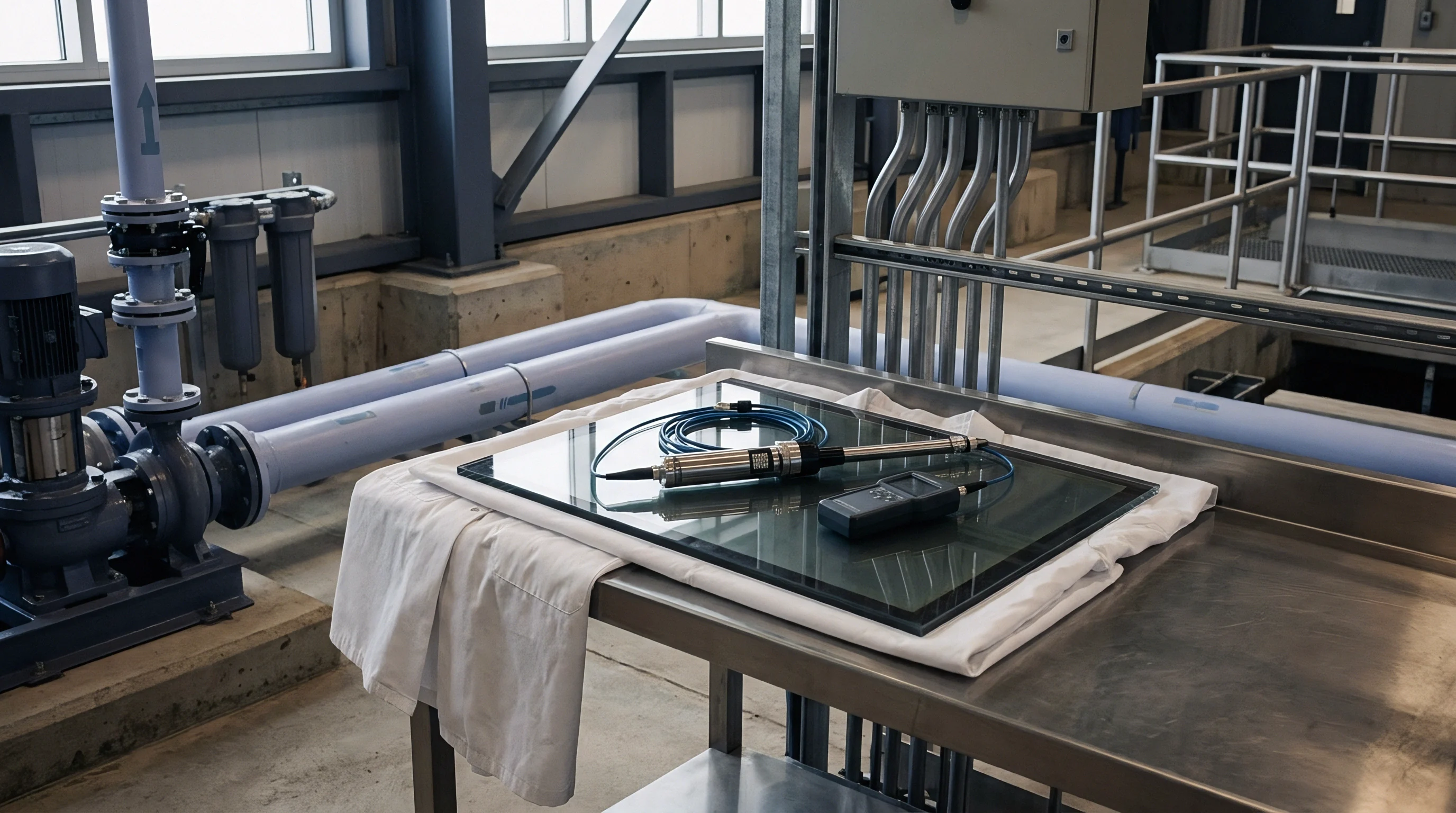
Maintaining tight shear control requires real-time telemetry monitoring paired with disciplined physical auditing. Mechanical pressure gauges installed on main pump lines deteriorate rapidly in acidic or alkaline chemical environments. Diaphragm seals, magnetic flow meters, and inline ultrasonic velocity sensors provide stable metrics without exposing sensitive instrumentation to aggressive electrolyte baths.
Weekly auditing routines must verify physical pump output against digital telemetry screens. Impeller erosion, filter bag clogging, and inner pipe scaling gradually restrict fluid velocity long before centrifugal pump motors show electrical overload. A ten percent reduction in volumetric flow rate shifts localized fluid regimes from turbulent to transitional, expanding the Nernst boundary layer and triggering unexpected pinhole defects.
| Parameter | Target Range | Sensor Mechanism | Audit Cadence | Action Limit |
|---|---|---|---|---|
| 0.14 – 0.16 MPa | PVDF Diaphragm Gauge | Daily Shift Start | < 0.12 MPa | |
| 0.8 – 1.2 m/s | Inline Ultrasonic Meter | Continuous Telemetry | < 0.7 m/s | |
| 0.02 – 0.05 MPa | Dual Pressure Transducer | Twice Daily | > 0.08 MPa | |
| 1.15 – 1.25 cSt | Rotational Viscometer | Weekly Lab Titration | > 1.35 cSt |
Operational Decision Parameters for Flow Adjustments
Process engineers balance multiple mechanical and chemical parameters when optimizing bath shear dynamics for new component geometry. The following decision checklist guides line adjustments prior to signing off on pilot runs:
- Substrate Aspect Ratio dictates nozzle angle selection, requiring narrower impingement angles for deeper geometry.
- Bath Viscosity Variations resulting from high salt concentrations demand increased pump discharge head pressure to maintain target velocity.
- Rack Loading Density alters fluid pathways, requiring elevated volumetric flow rates when processing dense part configurations.
- Part Orientation Angles must tilt fifteen degrees relative to primary fluid streams to prevent liquid trapping in cup-shaped features.
What uncalibrated fluid dynamic interactions occur when bath temperatures drop five degrees below nominal target during winter morning restarts?
Invoice
Chemical Drag-Out Economics and Fluid Shear Mechanics
Electrolyte shear dynamics directly govern drag-out volume when plating racks exit liquid chemical tanks. Higher bath fluid movement reduces the boundary layer thickness of static liquid clinging to parts as they break the bath surface. Excessive flow turbulence near liquid surfaces creates surface ripples and foam, increasing liquid film capture on upper rack structures.
Drag-out chemical loss represents a massive recurring line item on cross-border manufacturing invoices. Consider an automated reel-to-reel nickel plating line operating in Shenzhen at twenty meters per minute, processing 500,000 square meters of stamped leadframes monthly. Liquid film retention without optimized shear control carries 25 milliliters of electrolyte per square meter out of the main bath into rinse tanks.
At a bath chemical cost of 4.20 USD per liter, raw chemical loss equals 52,500 USD per month.
Optimizing eductor flow dynamics and exit zone liquid air-knives compresses surface film retention down to 10 milliliters per square meter. This fluid dynamic correction reduces liquid drag-out by sixty percent, lowering monthly chemical replenishment costs to 21,000 USD while reducing wastewater treatment neutralizer consumption by 14,000 USD monthly. The combined annual savings of 546,000 USD pays for complete pump, eductor, and flow control retrofits within forty-five operating days.
Standard supply agreements under ISO 14001 compliance standards assign total financial liability for excess chemical sludge disposal to the facility operator when drag-out rates exceed 15 milliliters per square meter.
Scrap Allocation and Rework Liability Clauses
Uncontrolled shear variation drives high scrap rates that undermine component profit margins. Contract agreements between brand buyers and contract plating facilities must explicitly define acceptable thickness tolerance bands and assign financial scrap ownership when defects originate from poor fluid agitation management.
Standard quality annex clauses in commercial contracts establish explicit technical liabilities for shear defects:
Where electroplating defect rates exceed 1.5 percent per batch due to non-uniform coating thickness, pinholes, or edge burning resulting from inadequate tank agitation, the supplier assumes full cost of chemical stripping, mechanical re-polishing, substrate replacement, and third-party laboratory verification testing.
Embedding specific shear telemetry compliance metrics into master service agreements provides buyers clear commercial leverage when bath maintenance lapses produce out-of-spec components.