Electrodeposited Copper Additive Dynamics in Printed Circuit Board Fabrication
Controlled additive balance between suppressors, accelerators, and levelers drives bottom-up microvia filling, requiring strict CVS control to avoid scrap.


Electrolyte
Acid copper plating baths rely on a four-component organic package dissolved in an aqueous matrix of copper sulfate and sulfuric acid to fill blind microvias and plate through-holes uniformly. Sulfuric acid maintains bath conductivity while lowering the cathodic potential, allowing copper ions to deposit under controlled electric fields. Copper sulfate supplies the cupric ions consumed at the board surface during continuous galvanic reduction.
Inorganic chloride ions operate at concentrations between 40 and 80 milligrams per liter, acting as an electrostatic bridge between the cathode surface and organic additives. Without chloride ions within this strict bracket, organic levelers and suppressors lose their anchoring potential, resulting in nodular copper growths and severe surface roughness across printed wiring boards.
Organic additives govern the local deposition rate by segregating into species that retard or promote copper reduction under local hydrodynamic regimes. Suppressors, typically high molecular weight polyoxyethylene glycols or polyalkylene glycols ranging from 2,000 to 10,000 grams per mole, adsorb onto the copper surface in conjunction with chloride ions. This combined film creates an ohmic barrier that increases cathodic overpotential by 150 to 250 millivolts, suppressing electrodeposition across open planar surfaces.
Accelerators, principally bis(3-sulfopropyl) disulfide or 3-mercapto-1-propanesulfonic acid, displace suppressors at high-curvature regions where mechanical shear remains low. Levelers, consisting of nitrogen-containing heterocyclic compounds, phenazine dyes, or quaternary amine polymers, migrate under diffusion control to high-fluid-shear peaks to inhibit localized charge transfer.
Chloride mediates additive adsorption onto copper.
The functional interactions between these chemical agents dictate whether blind microvias plate into solid copper pillars or entrap electrolyte inside unfilled voids. Plating bath formulators balance the molar ratios of accelerator to suppressor so that microvia bottoms experience acceleration while outer copper foil surfaces experience sustained suppression. When chemical consumption depletes the accelerator below its nominal target, copper deposition slows across every feature, producing thin surface plating and unfilled via hollows.
Conversely, excess accelerator strips suppressor molecules from planar regions, inducing massive copper thickness variation across high-density circuit layouts.
| Chemical Component | Typical Concentration | Primary Overpotential Impact | Diffusivity in Plating Bath (cm²/s) | Adsorption Mechanism |
|---|---|---|---|---|
| Copper Sulfate (CuSO₄·5H₂O) | 60 to 220 g/L | Cathodic polarization baseline | 5.8 × 10⁻⁶ | Solvated ion mass transfer |
| Sulfuric Acid (H₂SO₄) | 40 to 180 g/L | Reduces solution resistance | 2.1 × 10⁻⁵ | Hydronium proton transport |
| Chloride Ion (Cl⁻) | 40 to 80 mg/L | Co-catalyst polarization shift | 1.5 × 10⁻⁵ | Specific chemisorption on cathode |
| Suppressor (PEG/PPG copolymer) | 100 to 800 mg/L | Increases overpotential (+200 mV) | 2.4 × 10⁻⁷ | Chloride-bridged physical film |
| Accelerator (SPS / MPS) | 2 to 15 mg/L | Decreases overpotential (-120 mV) | 4.1 × 10⁻⁶ | Displaces suppressor under low shear |
| Leveler (Polymeric Quaternary Amine) | 1 to 10 mg/L | Increases local overpotential (+80 mV) | 3.2 × 10⁻⁷ | Convection-limited mass transfer |
Plating current forces copper ion migration.
Controlling this chemical equilibrium demands continuous replenishment based on ampere-hour consumption profiles. Commercial automated dosing units monitor the current delivered through rectifiers, injecting proprietary replenishment stock solutions calibrated to empirical depletion curves. Chemical consumption rates deviate significantly under alternating board designs, especially when alternating between dense outer-layer microvia arrays and plain core distribution panels.
A buyer auditing a facility in the Pearl River Delta verifies whether the line runs on fixed volumetric schedules or dynamic ampere-hour calculations.
A total organic carbon reading exceeding 3.5 grams per liter in an acid copper bath correlates with a twenty-four percent drop in plated ductile elongation.
Organic breakdown products poison copper deposits.
Uncontrolled chemical imbalances transform plating baths into scrap-generating vessels, where entire plating racks emerge with irregular dimpling, excessive surface copper thickness, and microstructural voids that cause catastrophic delamination during subsequent reflow assembly cycles.

Bore
Microscopic blind vias present severe mass-transport limitations that alter the local concentration of copper ions and organic additives relative to the bulk solution. When an outer panel layer enters the plating tank, fluid movement across the laminate surface drives convective flow over the surface foil while leaving stagnant fluid pockets inside microvias below 100 micrometers in diameter. Fluid velocities drop from 0.8 meters per second in the outer channel to under 0.005 meters per second within the lower third of a blind via bore.
This velocity drop causes the diffusion layer thickness inside the hole to expand beyond twenty micrometers, restricting the replenishment of cupric ions from the bulk fluid.
Copper ions deplete rapidly inside microvias.
The Curvature Enhanced Accelerator Coverage model explains how microvias achieve bottom-up filling under proper additive balance. As copper begins plating onto the curved bottom and sidewalls of the via, the total internal surface area contracts. Suppressor molecules, having high molecular weight, exhibit slow adsorption kinetics and low desorption rates.
Accelerators, by contrast, remain adsorbed to the moving copper growth front without desorbing into the liquid phase. As the via volume fills and the internal surface area decreases, the local surface concentration of accelerator increases exponentially. This concentrated accelerator cluster displaces remaining suppressor molecules, creating a hyper-active deposition zone at the bottom of the via while planar surfaces remain suppressed by continuous convective leveler flux.
Convection sweeps levelers toward board surfaces.
Where Fails Bottom up Microvia Filling?
Bottom-up filling breaks down whenever leveler molecules penetrate into the bottom of the blind hole or when cupric ion replenishment drops below the threshold required to sustain accelerated deposition. If fluid agitation within the tank pushes leveler additives into the lower third of the via, the leveler suppresses the accelerator, equalizing copper deposition rates between the bottom and the top rim. The via opening then pinches shut before the base fills, trapping air, plating chemistry, and organic debris within an internal cavity.
This defect mode remains invisible during visual surface inspection, revealing itself only under destructive micro-sectioning or automated scanning acoustic microscopy.
Brightener molecules accumulate at high-curvature corners.
The geometry of the bore dictates the convective boundary conditions. Aspect ratios exceeding 0.8 to 1 in blind microvias or 10 to 1 in through-holes require modified chemical dynamics and tailored fluid delivery systems. Specialized eductor agitation nozzles, oriented at forty-five-degree angles to the moving panels, sweep fluid across the panel surface to thin the boundary layer.
When a facility processes high-density boards using standard air-sparging rather than controlled liquid eductor banks, fluid stagnation inside blind microvias prevents accelerator accumulation. Copper builds uniformly on the sidewalls until a central void forms, cutting mechanical reliability under thermal shock.
- Convective Mass Transfer Suppression restricts leveler transport into blind microvias while maximizing leveler concentration on outer planar copper surfaces to maintain low baseline growth rates.
- Area Reduction Concentration Dynamics force accelerator molecules to compress into smaller surface areas at the via base, multiplying the local exchange current density.
- Boundary Layer Thinning achieved through directional eductor manifolds delivers uniform cupric ion concentrations across panel surfaces without flushing active accelerator molecules from via bottoms.
- Chloride Displacement Resistance maintains the stable adsorption of polyoxyethylene glycol complexes across board surfaces while permitting accelerator displacement inside feature cavities.
Blind via geometry interacts with the electric field distribution across the cathode rack. Current density naturally concentrates at feature corners, creating an electrostatic field that attracts positively charged leveler species. This localized current accumulation accelerates copper deposition at the via rim unless levelers successfully polarize these regions.
When leveler concentration drops by as little as two parts per million, the rim plates faster than the base, sealing the mouth of the microvia prematurely. Destructive cross-sections then show classic hourglass or pinch-off voids.
Maintaining bottom-up filling across an eighteen-by-twenty-four-inch production panel demands balanced chemical diffusion, electric field uniformity, and fluid shear across every square centimeter of the submerged substrate.
Assay
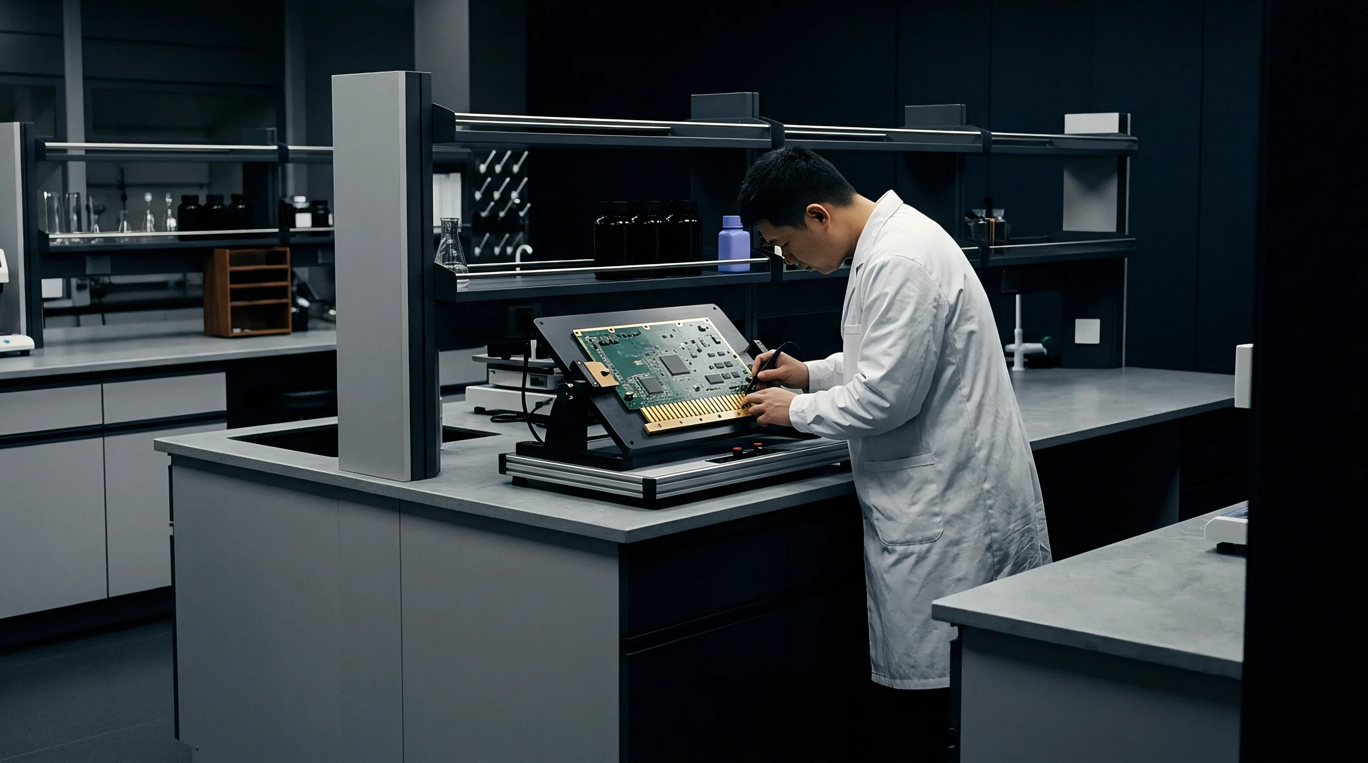
Laboratory control of acid copper additives relies on electrochemical techniques capable of isolating the dynamic behavior of individual organic components within complex production baths. Standard spectroscopic and chromatographic methods fail because additives function at parts-per-million levels alongside hundreds of grams per liter of inorganic salts. Cyclic Voltammetric Stripping remains the standard analytical method across global circuit board operations.
A rotating platinum disc working electrode alternates between cathodic potentials to deposit copper and anodic potentials to strip it off, measuring the electrical charge passed during stripping cycles. The ratio of stripping charge between clean calibration standards and working bath samples reveals the active concentration of accelerators and suppressors.
Clean baths yield uniform grain structures.
Cyclic Voltammetric Stripping operates through distinct analytical modes to isolate components. The Linear Approximation Technique or Dilution Titration measures suppressor concentration by titrating a known volume of bath sample into a base electrolyte, recording the suppression of stripping peak areas as the polymer forms an insulating monolayer on the rotating platinum electrode. Accelerator determination uses the Modified Linear Approximation Technique, adding small quantities of accelerator standard into a suppressed base solution to observe the restoration of stripping current.
Leveler concentration measurement relies on the Quality Control Leveler technique, where high rotation speeds force convective mass transfer to quantify leveler suppression in the presence of excess accelerator.
IPC-6012 Class 3 requires zero internal voiding within plated microvias after six consecutive thermal shock floating cycles at 288 degrees Celsius.

Is Cyclic Voltammetric Stripping Sufficient Alone?
Evaluating bath health requires analytical tools beyond Cyclic Voltammetric Stripping, because CVS measures only net electrochemical activity rather than molecular chemical structure. As organic molecules endure continuous electrical current, chemical bonds cleave, producing breakdown metabolites such as sulfinic acid derivatives, polyether fragments, and charged amine monomers. These breakdown products mimic the active polarization signatures of virgin additives during CVS sweeps, giving false readings of bath stability while degrading physical deposit ductility and microvia filling capacity.
Facilities running high-reliability production lines operate High-Performance Liquid Chromatography alongside CVS to quantify the accumulation of inactive organic breakdown fragments.
Line operators silence dosing pump alarms.
Establishing an audit cadence for bath analysis separates high-yield facilities from operations that suffer periodic yield collapses. High-density interconnect fabricators in Jiangsu and Guangdong test active plating lines twice per eight-hour shift using automated CVS instruments, accompanied by daily Hull cell testing to verify visual plating aesthetics across varied current densities. Hull cell panels, plated across a current gradient from 0.5 to 5.0 amperes per square decimeter, reveal burning at high current zones, haze at low current zones, and pitting caused by organic decomposition products.
- The shift technician draws a fifty-milliliter electrolyte sample from the tank recirculation manifold after confirming continuous agitation for at least thirty minutes.
- The technician runs a three-point calibration curve on the Cyclic Voltammetric Stripping unit using certified chemical reference standards maintained at twenty-two degrees Celsius.
- The technician executes dilution titrations for suppressor, accelerator, and leveler compounds, comparing calculated consumption against the ampere-hour meter log.
- The technician logs deviations exceeding fifteen percent from baseline into the facility quality system, locking the auto-replenishment pumps to prevent automated chemical over-dosing.
- The engineering supervisor reviews cross-section coupons from the previous production lot before clearing the plating line to accept subsequent panel batches.
Voltammetric peaks shift under bath contamination.
When analytical deviations appear during shift handovers, line managers often state that minor additive imbalances will self-correct once fresh replenishment chemistries circulate through the continuous carbon filtration packs over the weekend.

Fault
Mechanical failures in plated copper microvias stem directly from improper additive consumption ratios and unmonitored bath contamination. When plating lines run with depleted levelers or excessive brighteners, the copper matrix exhibits pronounced structural and morphological defects. Dimpling, characterized by a depressed surface profile over the filled via, occurs when the bottom-up growth rate fails to outpace planar deposition.
IPC-6012 sets strict limits on dimple depth, typically mandating that surface depressions not exceed five to ten micrometers depending on the specified reliability class. Vias with excessive dimple depth collect solder paste unevenly during surface-mount assembly, creating solder bridging or non-wet open joints under fine-pitch ball grid array components.
Dimples scrap high-density interconnect panels immediately.
Internal voiding represents a more destructive failure mechanism. Central seam voids form when sidewall plating velocities exceed bottom growth, sealing an air pocket inside the feature. Wedge-shaped voids emerge along via corners when organic leveler contaminants accumulate at structural interfaces, disrupting epitaxial copper grain growth.
These internal voids expand during component assembly soldering temperatures, generating internal vapor pressure that ruptures adjacent dielectric resin layers or cracks the plated copper barrel. Destructive micro-section testing conducted per IPC-TM-650 Method 2.1.1 uncovers these internal defects through sequential grinding, polishing, and chemical etching.
A plating bath containing eighty milligrams per liter of chloride exhibits twice the leveler adsorption stability of a bath operated at thirty milligrams per liter.
Carbon treatment strips active organics completely.
| Defect Classification | Visual / Cross-Section Morphology | Chemical Additive Root Cause | IPC-TM-650 Test Method | Lot Rejection Criteria |
|---|---|---|---|---|
| Central Seam Void | Linear enclosed void along vertical axis of via | Excess leveler or insufficient accelerator concentration | 2.1.1 Microsectioning | Any void exceeding 5% of via volume |
| Inclusion Defect | Dark organic particulate embedded in copper matrix | Accumulated additive breakdown products (>4 g/L TOC) | 2.1.1 Optical Microscopy | Presence of non-metallic grain inclusions |
| Excessive Dimple | Surface hollow over via center deeper than 15 µm | Low accelerator activity or low bath operating temperature | 2.2.18 Surface Profile | Dimple depth > 10 µm (IPC Class 3) |
| Nodular Surface | Rough, cauliflower-like copper lumps on foil | Chloride depletion below 30 mg/L or excess leveler | 2.1.1 Metallographic Inspection | Surface roughness exceeding Ra 1.2 µm |
| Corner Cracking | Separation between target pad and microvia base | High internal tensile stress from leveler co-deposition | 2.6.8 Thermal Stress | Any crack visible after 6x reflow shocks |
| Thermal stress tests conducted after conditioning specimens at 105°C for 2 hours, followed by solder float at 288°C for 10 seconds. | ||||
Process audits expose silent chemical adjustments.
Copper microstructure dictates long-term reliability in the field. High-reliability circuit boards require equiaxed, fine-grained copper with tensile elongation exceeding eighteen percent and tensile strength above 275 megapascals, as measured by IPC-TM-650 Method 2.4.18. When leveler molecules or sulfur from accelerator breakdown co-deposit into the copper crystal lattice, they pin grain boundaries, creating brittle columnar microstructures.
Under thermal cycling between minus forty and plus one hundred and twenty-five degrees Celsius, these brittle copper matrices fail along grain boundaries, severing electrical continuity inside mission-critical systems.
- Thermal Shock Resistance requires fine-grained equiaxed copper deposits capable of absorbing mechanical strain induced by z-axis thermal expansion in high-Tg FR-4 laminates.
- Chemical Bath Turnover Tracking eliminates brittle copper deposition by forcing complete carbon-treatment cleanouts whenever total organic carbon reaches defined thresholds.
- Incoming Coupon Cross-Sectioning identifies interfacial separation between the microvia base and capture pad before panels pass to automated solder masking.
Soothed panels fail thermal stress screening.
Under Section 3.6.2 of the standard IPC-A-600 qualification framework, any evidence of interfacial separation, plating micro-voids, or barrel cracks across sample micro-section coupons authorizes the buyer to reject the entire production master lot immediately at the supplier dock.

Settlement
Managing acid copper additive performance across offshore supply chains requires structural financial controls tied directly to laboratory logging and scrap attribution. Circuit board fabricators operate under thin gross margins, creating strong internal incentives to extend plating bath operational life far past recommended carbon-treatment intervals. Running an electrolyte solution past six bath turnovers saves the factory thousands of dollars in chemical replacements and hazardous liquid waste disposal fees.
The downstream cost lands on the offshore buyer in the form of latent solder joint failures, high-temperature assembly rejects, and unrecoverable warranty claims.
Distance inflates scrap disposal charges.
A rigorous supply contract links invoice reconciliation to verified chemical process data. Buyers who audit facilities in Shenzhen or Kunshan establish inspection frameworks requiring fabricators to upload shift-by-shift CVS logs, ampere-hour depletion charts, and daily Hull cell test coupons into a shared digital quality docket. If a supplier fails to upload CVS records for three consecutive production shifts, the contract triggers an automatic hold on pre-shipment sign-offs.
Physical presence remains irreplaceable during process drift events; sending an engineer to audit the chemical warehouse, inspect replenishment drum seals, and watch a technician calibrate the CVS electrode prevents suppliers from masking chemistry exhaustion with cosmetic bleaching agents.
Consider a standard production run to evaluate the commercial stakes of bath maintenance. A mid-sized fabricator runs twenty thousand high-density interconnect panels monthly across two automated plating lines, with bare board manufacturing costs pegged at forty-two dollars per panel. When additive decomposition increases internal microvia voiding from 0.5 percent to 4.2 percent, the scrap rate climbs by 740 panels in a single monthly production cycle.
The raw manufacturing loss reaches $31,080 per month in scrapped laminate and copper foil. If those defective boards pass visual inspection and enter customer assembly lines before thermal stress cracks emerge, rework and component loss escalate costs above one hundred and sixty dollars per assembled board.
Contractual warranties must shift financial liability for chemistry-induced defects onto the board fabricator. Standard master services agreements often contain vague clauses committing the supplier to general workmanship standards. Experienced offshore procurement teams replace these generalizations with clear indemnification language defining specific chemical failure triggers.
The contract specifies that any lot displaying average dimple depths exceeding eight micrometers or any internal microvia voiding during IPC-TM-650 micro-section audits authorizes the buyer to deduct the full replacement cost, incoming inspection fees, and secondary air-freight charges directly from open accounts payable.
Plating baths maintained with fresh organic additives and disciplined filtration yield pristine metallurgical joints without requiring endless disputes over incoming scrap.