Correlating Submicron Interface Void Densities with Long Term Thermal Fatigue Creep Failure Kinetics
Submicron interface void arrays magnify local stress tensors, accelerating creep cavitation and cutting power module thermal fatigue lifespan by over sixty percent.


Bond
High-power silicon carbide and gallium nitride semiconductor packages rely on metallic interphase contacts to transmit thermal energy while sustaining structural shear loads. Submicron interfacial void arrays ~ pore networks with equivalent spherical diameters between 50 and 500 nanometers ~ alter the local stress tensor across the die-attach footprint. Initial submicron void area fraction and spatial clustering determine when creep cavitation begins during thermal cycling.
As an operating device cycles between temperature extremes, strain concentrates along microstructural discontinuities in the interphase line, where submicron pores act as stress risers that elevate local elastic-plastic deformation rates above bulk material predictions.
These void networks function as local stress risers across the joint.
In silver and copper direct-bonded substrate interfaces, void networks reduce the effective load-bearing area. Local stress concentration factors around submicron void arrays typically range from 2.5 to 4.8 times the nominal applied shear stress, depending on matrix pore spacing and grain boundary orientation. Geometry dictates damage accumulation: while evenly distributed submicron pores spread strain energy across the contact interface, clustered voids form localized plastic shear zones that accelerate crack initiation.
A three percent increase in submicron void density at the substrate joint elevates localized thermal resistance by 18 percent under passive temperature cycling from -40°C to 150°C.
Thermo-mechanical fatigue driven by thermal expansion mismatches between the semiconductor die, interphase material, and direct copper bonded ceramic substrate generates cyclic shear strain. Creep operates continuously at elevated junction temperatures, where vacancy diffusion along high-energy grain boundaries feeds submicron void growth under sustained thermal loads. High local stress surrounding micro-voids drives dislocation climb and glide, initiating intergranular micro-cracks well before macroscopic delamination shows up on acoustic scans.
| Joint Metallurgy | Mean Void Diameter (nm) | Initial Void Density (pores/µm²) | Stress Concentration Factor | Dominant Creep Mechanism |
|---|---|---|---|---|
| Pressureless Silver Sinter | 120 – 350 | 1.8 – 4.2 | 2.8 – 3.4 | Coble Grain Boundary Diffusion |
| Pressurized Copper Sinter | 60 – 180 | 0.4 – 1.1 | 2.1 – 2.6 | Nabarro-Herring Lattice Diffusion |
| Transient Liquid Phase (Cu-Sn) | 200 – 480 | 2.5 – 5.8 | 3.6 – 4.5 | Dislocation Climb Assisted Glide |
| Lead-Free Solder (SAC305) | 300 – 800 | 0.9 – 2.3 | 3.1 – 3.9 | Matrix Grain Boundary Sliding |
Specifying initial void density tolerances without accounting for pore spacing distributions leads to premature thermal runaway failures, excessive warranty claims, and field recalls in high-reliability power applications.

Sinter
Thermal processing schedules dictate the initial morphology of submicron void networks within power module interfaces. Organic binder burnout during pressureless thermal cycles generates internal gas pressure within micro-capillaries when heating rates outpace solvent evaporation. Trapped gas prevents metallic neck growth between powder particles, locking micro-cavities into the solidified joint interphase.
Local variations in clamping pressure during thermal pressing also produce density gradients across large substrate contacts.
Thermal gradients across the package drive continuous atomic flux.
Tooling alignment drift, thermal mass variations across multi-cavity fixtures, and heating element degradation all introduce interface density variations. Pressure profiles across automated press heads frequently shift over a production run, where a ten percent drop in local consolidation pressure can increase the submicron void population along die edges by an order of magnitude.
- Binder burnout entrapment occurs when organic vehicle decomposition rates outpace volatile gas diffusion paths through the consolidating powder compact.
- Pressure profile tilt arises from mechanical compliance misalignments across automated heating platen arrays, generating void concentration gradients.
- Surface oxide inhibition blocks atomic transport across metallic particle boundaries, leaving submicron channels unsealed during thermal exposure.
- Particle size segregation creates localized regions of low packing density within the wet paste deposit prior to thermal processing cycles.
Compliance with IPC-A-610 Class 3 interface criteria fails to prevent creep failure when void sizes drop below the optical acoustic resolution limit.
Submicron defect networks often remain stable during factory testing, only to become primary failure sites under long-term operational stress. Standard end-of-line functional checks miss submicron pore distributions because the initial electrical and thermal paths remain unbroken.
Extended thermal pressing dwell times are often taken to indicate joint integrity, but pressure distribution maps can still reveal localized low-density micro-zones across the contact substrate.

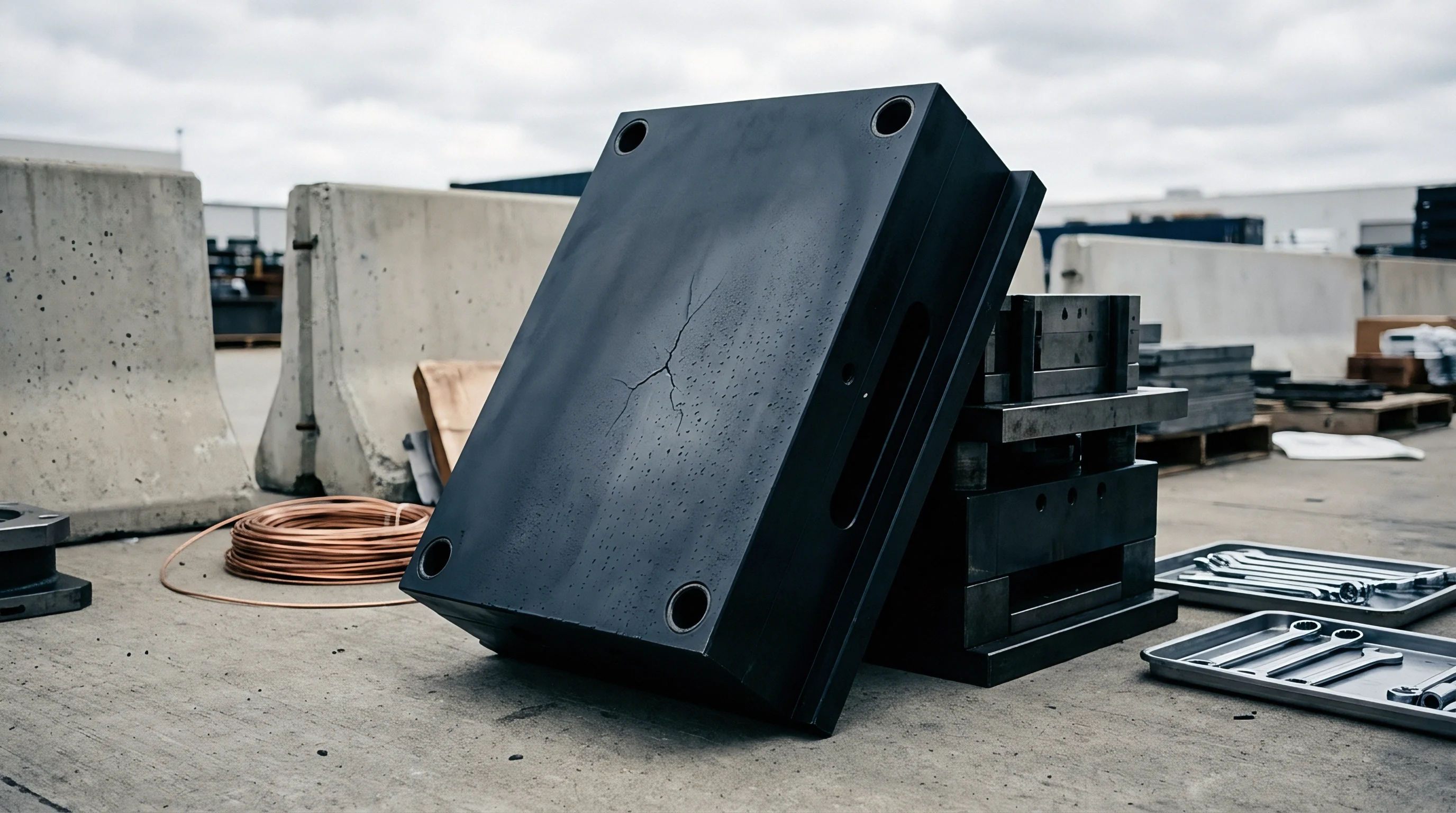
Strain
Viscoplastic strain accumulation during thermal fatigue changes the structural stability of interfacial submicron voids. As thermal cycling progresses, uniform matrix deformation breaks down into localized shear bands connecting adjacent submicron cavities. At high homologous temperatures, stress gradients drive atomic vacancy flux toward micro-void surfaces.
The rate of this vacancy absorption controls submicron void growth, turning isolated micro-cavities into continuous intergranular creep cracks.
Cracks tend to propagate directly along these void networks.

How Do Submicron Void Arrays Alter Localized Matrix Strain Rate?
Submicron void arrays increase local matrix strain rates by reducing the internal plastic shear resistance of the interphase material. The Anand viscoplastic constitutive model captures this behavior by incorporating crack nucleation damage parameters into deformation state variables. Amplified local strain accelerates grain boundary sliding, and as sliding continues, voids coalescing at grain triple junctions give rise to micro-cleavage planes.
- Quantify initial submicron void spatial density and mean volumetric diameter using serial sectioning high-resolution electron imaging profiles.
- Calculate localized stress concentration factors across the interphase matrix using finite element micro-structural sub-models.
- Input local stress tensors into the Riedel-Rice creep crack propagation formulation to establish cavitation growth rates.
- Integrate plastic strain energy density per thermal cycle to compute time-dependent micro-void coalescence boundaries.
- Map calculated damage accumulation thresholds against operational cycle requirements to determine fatigue life limits.
As these void networks expand, local material compliance changes accordingly.
Void array proximity accelerates grain boundary sliding faster than bulk grain coarsening under high-temperature fatigue.
Submicron void growth kinetics follow diffusional transport laws: elevated local stresses accelerate vacancy accumulation along grain boundaries regardless of macro-scale loading constraints.

Microscopy
Analytical quantification of submicron interface voids requires metrology instruments capable of resolving features below 100 nanometers across multi-layered electronic packages. Standard C-mode scanning acoustic microscopy operates at transducer frequencies between 15 and 230 megahertz, yielding spatial resolutions of 15 to 50 micrometers. This resolution limit lets submicron void arrays pass non-destructive acoustic inspections undetected, as acoustic waves traverse submicron pore clusters without producing measurable reflection signals, registering an artificially uniform interphase line on quality reports.
Empirical data confirms that the interphase boundaries shift during thermal exposure.
| Diagnostic Method | Spatial Resolution | Inspection Depth | Destructive Status | Sample Throughput |
|---|---|---|---|---|
| C-Mode Acoustic Microscopy (230 MHz) | 15 – 25 µm | Full Package Depth | Non-Destructive | 120 units/hour |
| High-Resolution X-ray Micro-CT | 0.5 – 1.2 µm | Substrate Level | Non-Destructive | 2 units/hour |
| Focused Ion Beam SEM Cross-Section | 3 – 5 nm | Surface Area 50×50 µm | Destructive | 1 unit/4 hours |
| Synchrotron X-ray Nano-Tomography | 30 – 80 nm | Targeted Sub-Volume | Non-Destructive | 1 unit/day |
Destructive physical analysis remains necessary to validate submicron interface density parameters. Focused ion beam milling paired with high-resolution scanning electron microscopy permits cross-sectional imaging of buried interphase structures without introducing mechanical smearing artifacts common to conventional metallographic polishing.
- Targeted ion beam cross-sectioning exposes pristine interphase planes without mechanically distorting soft submicron void boundaries during sample preparation.
- Automated image segmentation extracts void area fraction, equivalent circle diameter distributions, and nearest-neighbor distance metrics from electron micrographs.
- Synchrotron nano-tomography verification establishes three-dimensional volumetric calibration standards for laboratory X-ray inspection equipment.
At operating temperatures, vacancy diffusion becomes the dominant mechanism.
Scanning acoustic pulse reflections bypass sub-300 nanometer pore networks located along the intermetallic contact line.
Incorporating MIL-STD-883 Method 2030 addendums requiring high-resolution ion beam milling audits forces suppliers to maintain true submicron process controls rather than relying on acoustic screening limits.

Lifespan
Predictive life estimation models incorporate initial submicron void density terms to forecast long-term creep-fatigue interactions under field operating cycles. Traditional Coffin-Manson formulations underestimate damage accumulation by treating metallic interphases as homogeneous continuum solids. Modifying strain energy density models to include void volume fractions (fv) and void spacing ratios (Rs) provides accurate fatigue life predictions under combined power cycling and ambient temperature swings.
Defect-driven yield losses accumulate rapidly across production lots.
Inelastic strain energy density dissipated per thermal cycle increases exponentially as initial void density rises. Micro-voids decrease the effective cross-sectional area, increasing effective stress levels and accelerating creep strain rates according to power-law creep relations. Micro-void growth calculations show that initial submicron void densities above 2.5 percent reduce operational thermal fatigue life by more than 60 percent compared to fully dense interface baseline profiles.
| Initial Void Density (%) | Mean Pore Spacing (nm) | Accumulated Creep Strain/Cycle (%) | Cycles to Crack Initiation (-40/150°C) | Projected Field Life (Years) |
|---|---|---|---|---|
| 0.2 | 850 | 0.012 | 14,500 | 22.5 |
| 0.8 | 420 | 0.028 | 9,200 | 14.2 |
| 1.5 | 260 | 0.055 | 5,100 | 7.8 |
| 3.2 | 110 | 0.142 | 1,800 | 2.7 |
Ultimately, the spatial distribution of these pores determines component life.
Unresolved questions persist regarding the precise vacancy diffusion interaction mechanisms operating at grain boundary intersections under simultaneous high-voltage electric fields and high thermal gradients.

Dossier
Converting submicron void density requirements into enforceable manufacturing quality specifications requires explicit contractual controls and verified audit schedules. Factory documentation must define sampling frequencies, preparation procedures, and image processing methodologies used to measure interface density metrics. Quality control plans that rely exclusively on non-destructive acoustic testing allow high-risk submicron void distributions to reach final assembly lines.
The choice of audit sample size directly shifts quality exposure.
An effective quality agreement addendum establishes precise acceptance thresholds for submicron void parameters. The technical dossier specifies focused ion beam sectioning requirements for every five thousand production modules or every raw material paste batch changeover. Failure to meet submicron void density limits triggers immediate line-stop authority and lot containment protocols.
Unmitigated submicron defects typically drive early field returns.
A worked financial assessment highlights the commercial imperative of submicron defect control. Consider a production run of 50,000 power modules deployed in automotive traction inverters. Standard C-SAM inspection costs approximately $1.50 per unit, while implementing a high-resolution destructive audit sampling protocol adds $0.45 per unit across the total build volume.
Assuming a 1.8 percent field failure rate over seven years resulting from unmonitored submicron void growth, total warranty replacement, logistics, and labor claims average $12,500 per failed module, totaling $11.25 million in commercial exposure. Spending $22,500 on destructive metrology controls during initial manufacturing prevents early field creep failures, preserving long-term operating margins and vendor qualification standing.
Implementing continuous microstructural verification controls bridges the gap between lab-scale reliability physics and high-volume packaging manufacturing lines.